Warning! The car models covered in this manual are equipped with an additional security system (SRS). Disable the SRS before doing any work near the airbag unit, steering column, or instrument panel to prevent injury from accidental deployment. SRS circuit wiring is easily identified by the yellow color of the insulation.
Combination switch
Examination
1. Disconnect the negative cable from the battery and wait at least three minutes before removing the trim.
Attention! If the stereo system installed in the car is equipped with a security code, before disconnecting the battery, make sure that you have the correct combination to activate the audio system!
2. Remove the combination switch assembly (see subsection below Replacement).
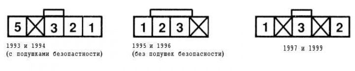
3. Using an ohmmeter or a probe lamp equipped with an individual power source, check the correct distribution of conductivity between the switch terminals in its various positions.
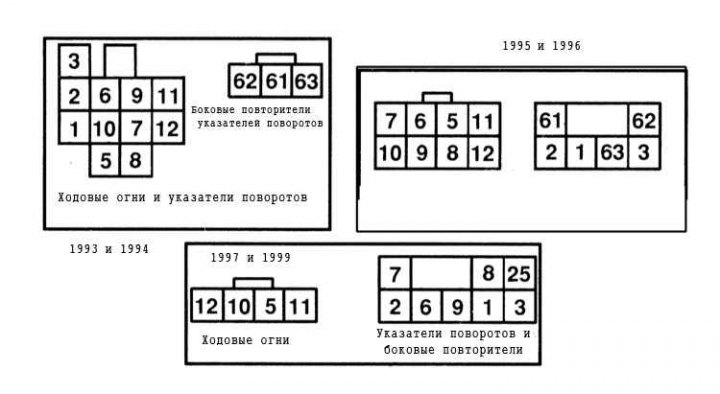
| Switch position | Conductivity between terminals |
| Headlights off, position C | 5 and 6, 8 and 9 |
| Parking lights, position A or B | 11 and 12 |
| Parking lights, position C | 5 and 6, 8 and 9, 11 and 12 |
| Headlights, position A or C | 5 and 6, 8 and 9, 11 and 12 |
| Headlights, position B | 5 and 7, 8 and 10, 11 and 12 |
| Headlights, position C | 5 and 6, 8 and 9, 11 and 12 |
| Right turn indicators | 1 and 2 |
| Left turn indicators | 1 and 3 |
| Right Turn Signals/Side Repeater | 61 and 62 |
| Left Turn Signals / Side Repeater | 61 and 63 |
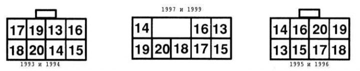
| Switch position | Conductivity between terminals |
| Off | 13 and 14 |
| Interval mode | 13 and 14, 15 and 17 |
| Slow mode | 17 and 17 |
| Quick mode | 16 and 17 |
| glass washing | 17 and 18 |
4. In case of detection of violations, replace the switch.
Replacement
1. Disconnect the negative cable from the battery and wait at least three minutes before removing the trim.
Attention! If the stereo system installed in the car is equipped with a security code, before disconnecting the battery, make sure that you have the correct combination to activate the audio system!
2. Remove the steering wheel (see chapter Suspension and steering).
3. Remove the driver's knee brace and steering column shroud covers (see chapter Body).
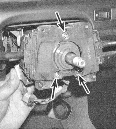
4. Turn out four fixing screws and remove the spring contact of a driver's airbag from the combined switch (see chapter Suspension and steering). Turn out screws of fastening of assembly of the combined switch.
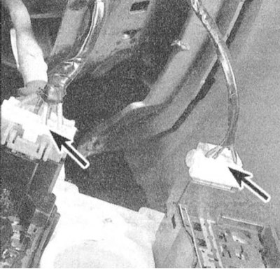
5. Remove assemblage of the combined switch from a steering column and disunite contact sockets of an electroconducting.
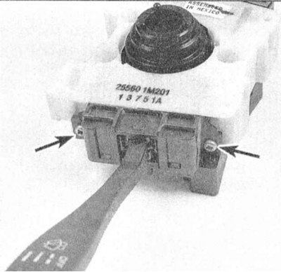
6. Turn out screws of fastening of the individual switch which is subject to replacement and remove the last from the case of the combined switch.
7. Connect the new switch to the terminals of the contact connector - make sure that the assembly is securely fixed in the block.
8. Further assembly is carried out in the reverse order to the dismantling of the components. Description of the procedure for installing the spring contact of the airbag is given in Chapter Suspension and steering.
Speed Control Switches
Examination
1. Panel of switches for controlling the functioning of the tempostat (Except On/Off switch) installed on the right side of the steering wheel of the car.
2. Remove the switch (see below). Using an ohmmeter or a probe lamp equipped with an individual power source, check the correct distribution of conductivity between the switch terminals in its various positions.
| Switch position | Conductivity between terminals |
| Resume/Accel (Return / Acceleration) | 1 and 3 |
| Set Coast (Installation/Coasting) | 1 and 2 |
| Cancel (Reset) | 1 and 3*, 1 and 2* (with diodes) |
* Diodes are used, check both directions
3. A defective switch must be replaced.
Replacement
1. Disconnect the negative cable from the battery and wait at least three minutes before removing the trim.
If the stereo system installed in the car is equipped with a security code, before disconnecting the battery, make sure that you have the correct combination to activate the audio system!
2. Using a screwdriver threaded into a special groove, remove the panel cover.
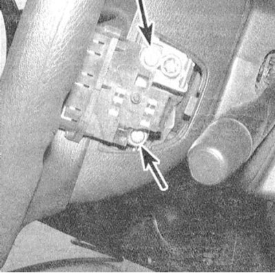
3. Turn out fixing screws, remove assembly of the switch and disconnect from it electroconducting.
4. Installation is carried out in the reverse order.