Warning! The car models covered in this manual are equipped with an additional security system (SRS). Disable the SRS before doing any work near the airbag unit, steering column, or instrument panel to prevent injury from accidental deployment. SRS circuit wiring is easily identified by the yellow color of the insulation.
1. The turn signal and alarm circuits use a common breaker.
2. The correct functioning of the interrupter is confirmed by a distinctly audible rhythmic click. The failure of one of the control lamps leads to the termination of the breaker. If one of the indicators fails, the breaker frequency doubles, informing the driver to replace the lamp.
3. Simultaneous failure of both indicators with a high degree of probability indicates the failure of the corresponding fuse. The possibility of failure of the breaker itself, or the steering column switch, is also not ruled out. Check up a condition of contact connections of electroconducting of a corresponding circuit. If a fuse blows, check the wiring for signs of a short circuit.
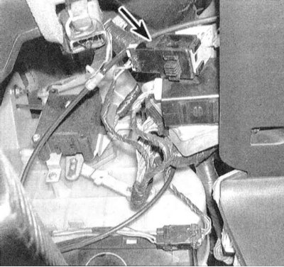
4. To replace the breaker, disconnect the electrical wiring from it and release the assembly from the support bracket located under the instrument panel, to the right of the steering column.
5. Make sure that the replacement breaker is of the same size as the failed one.
6. Installation is carried out in the reverse order.