


To adjust the start of fuel injection, turn the engine crankshaft until the piston of the first cylinder is set to the TDC position in the compression stroke, unscrew the central plug (Figure 1.41) on the fuel injection pump distributor head and install an indicator instead (figure 1.42)To set the pump plunger to the extreme position, turn the engine crankshaft counterclockwise by 25-30 degrees, using the installation groove on the crankshaft pulley as a guide (the piston is set to a position 25-30 degrees before TDC according to the angle of rotation of the engine crankshaft). Set the indicator readings to zero. Turn the engine crankshaft in both directions at small angles. If the pump plunger is really set to the extreme position, then when turning the crankshaft at small angles, the indicator arrow will not deviate. Different companies recommend setting the crankshaft counterclockwise at different angles (not less than 25 degrees), but the given testing method allows you to determine whether the shaft rotation angle is selected correctly to set the plunger to the extreme position. Next, turn the engine crankshaft clockwise (the piston moves in the direction of TDC) before installing the groove on the pulley against the TDC mark on the timing cover and using the indicator readings, determine the plunger stroke. Day of the LD20 engine (installed on NISSAN Bluebird Diesel) the plunger stroke should be 0.71-0.75 mm. If the plunger stroke does not correspond to the specified value, loosen the fuel pump mounting bolts and adjust the plunger stroke by turning the fuel pump in one direction or another, tighten the pump mounting bolts and repeat the check. The plunger stroke corresponds to a certain injection advance angle. Either the plunger stroke or the injection advance angle based on the engine crankshaft rotation angle is provided as reference data. For the same engine installed on different series of cars, the injection advance angles may differ. The exact data on the injection advance angle and the plunger stroke measurement point are indicated on the factory labels attached to the inside of the hood. The series of a specific car is also there.
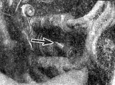
Figure 1.41. Unscrewing the plug on the high-pressure fuel pump
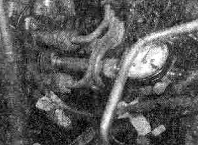
Figure 1.42. Installing a pressure gauge on the fuel injection pump
(Read more on the website: «NissanBook.ru»)
To check and adjust the engine idle speed, warm up the engine to normal operating temperature, disconnect the fuel supply control cable from the pump control lever, connect the tachometer in accordance with the instructions for its operation. Set the pump control lever to a position in which the idle speed adjustment screw touches the control lever (Figure 1.43). Start the engine, set the idle mode and check the engine crankshaft speed in this mode. If the obtained value does not meet the requirements for this engine, adjust the speed using the idle speed adjusting screw. The maximum engine crankshaft speed is adjusted in the same way, only when doing this, the fuel pump control lever is set to a position in which it touches the maximum speed adjustment screw, with which the adjustment is carried out if necessary. The idle speed for the LD20 engine is 650-750 rpm.
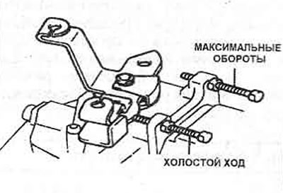
Figure 1.43. Fuel injection pump adjustment screws
After adjusting the maximum engine speed and idle speed, adjust the fuel control cable. Its length should ensure a light touch of the control lever and the maximum speed adjusting screw when the fuel control pedal is fully depressed, and a light touch of the lever and the idle speed adjusting screw when the pedal is lowered.
After completing the adjustment, check its correctness by the engine operation. Set the idle mode, smoothly press the gas pedal until reaching medium speed and sharply release the gas. If the idle mode adjustment is performed correctly, the engine will not stall.
On models with air conditioning, the engine crankshaft speed is adjusted with the air conditioning on. To do this, turn the idle speed control lever fully counterclockwise and adjust the gap between the idle speed control lever pin and the fuel pump control lever; the gap should be 1 mm. With the idle speed pre-adjusted, the specified gap value should ensure that the crankshaft speed with the air conditioning on is within 750-850 rpm. If necessary, adjust the speed with the screw. The speed in forced idle mode, i.e. the speed that is established after a sharp release of the gas, is adjusted with the adjustment screw. During operation, it is not recommended to adjust the speed at full load: this value is established during bench tests, and the full load speed adjustment screw is designed specifically for adjustment during bench tests. Violation of this adjustment will result in a violation of the fuel supply mode in all engine operating modes.