


Table of contents: Checking and adjusting ↓ Adjustment ↓
Checking and adjusting
Examination
If the camshafts or valve related components have been removed or replaced, or if engine operation deviates from normal values over time due to changes in valve clearances, check as follows:
1. Remove the valve cover. See below.
2. Measure the valve clearances as follows:
a. Set the piston of cylinder No.1 to TDC in the compression stroke.
- Turn the crankshaft pulley (1) clockwise and align the TDC mark (colorless risk) (B) with timing indicator (A) on the front cover.
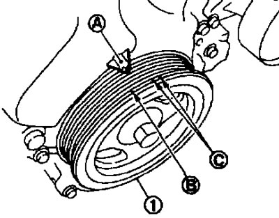
C. Mark with white paint (not used during maintenance).
- At the same time, make sure that the working projections of the camshafts of the intake and exhaust valves of cylinder No.1 are facing each other (
 ) as shown in the figure below. p.
 - Otherwise, rotate the crankshaft pulley one more revolution (360°) and insert them as shown in the figure on the next page.
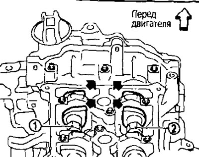
1. Intake camshaft.
2. Exhaust camshaft.
b. Using a feeler gauge, measure the valve clearances between the valve lifters and the camshaft.
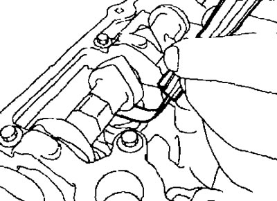
Riveted gaps: See Technical Data and Specifications section below.
Using the figure as a guide, measure the valve clearances using a feeler gauge at the locations marked with an "x" as indicated in Table No.1 below (in the picture the places are marked with black arrows).
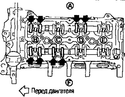
A. Issue side; In Cylinder No.1; From Cylinder No.2; D Cylinder No.3; E Cylinder No.4; P Inlet side.
c. Set the piston of cylinder No.4 to TDC, in the compression stroke.
Turn the crankshaft pulley (1) one revolution (360°) clockwise and align the TDC mark (colorless risk) (B) with timing indicator (A) on the front cover.
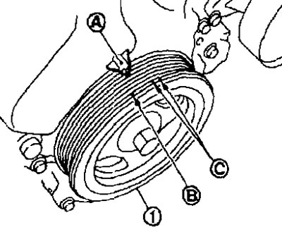
C. Mark with white paint (not used during maintenance).
Using the figure as a guide, measure the valve clearances using a feeler gauge at the locations marked with an "x", as indicated in Table No.2 below (in the picture the places are marked with black arrows).
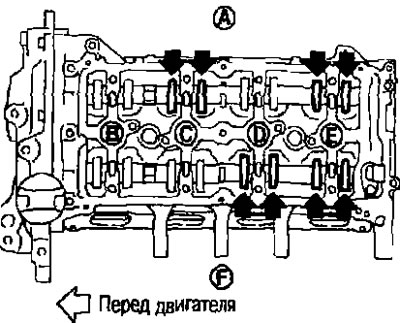
A. Issue side; B. Cylinder No.1; S. Cylinder No.2; D. Cylinder No.3; E. Cylinder No.4; F. Inlet side.
3. If the measured value is different from the norm, make adjustments. See below.
Adjustment
Make adjustments based on the selected valve tappet thickness.
1. Remove the camshafts. See below.
2. Remove the valve lifters whose clearances differ from the norm.
3. Using a micrometer (A), measure the thickness at the center of the removed valve lifters.
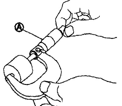
4. Calculate the thickness of the replacement valve tappet using the following formula:
Calculation of valve tappet thickness.
t-t1+(C1 - C2), where:
- t = Thickness of the replacement valve tappet.
- t1 = Thickness of the replacement valve tappet.
- C1 = Measured valve clearance.
- C2 = Standard valve clearance.
Inlet: 0.30 mm.
Issue: 0.33 mm.
- The thickness of the new valve tappet (B) can be determined by the marking (A) stamped on the back side (inside the cylinder).
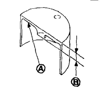
- The marking "302" means a thickness of 3.02 mm.
Note: Valve tappets are available in 26 thicknesses ranging from 3.00mm to 3.50mm in 0.02mm increments (during manufacturing at the factory).
5. Install the selected valve lifters.
6. Install the camshafts. See below.
7. Install the timing chain and related components. See below.
8. Turn the crankshaft pulley by hand a few turns.
9. Make sure the valve clearances are within specifications.
10. Install all removed components in the reverse order of removal.
11. Warm up the engine and check for any unusual noise or vibration.
Table No.1
| Place of measurement | Cylinder No.1 | Cylinder No.2 | Cylinder No.3 | Cylinder No.4 | |
| Piston of cylinder #1 at TDC in compression stroke | Release | X | X | ||
| Inlet | X | X | |||
Table No.2
| Place of measurement | Cylinder No.1 | Cylinder No.2 | Cylinder No.3 | Cylinder No.4 | |
| Piston of cylinder #4 at TDC in compression stroke | Release | X | X | ||
| Inlet | X | X | |||