


- Before installing piston rings, it is necessary to check the gaps between the ends of the rings. It is assumed that the piston ring lateral clearance has already been checked and is within the norm.
- Lay out the new pistons and rings so that the ring end clearance check is performed on the pistons and in the cylinders where the rings will be installed.
- Insert the upper (first) ring (2) into the first cylinder and position it perpendicular to the walls, pushing it with the piston (1).
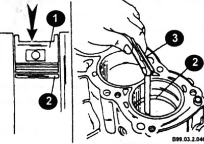
- The ring should be positioned near the extreme point of the ring's travel.
- To measure the gap between the ends of the rings, insert feeler gauges (3) of different thicknesses into the gap until you find a feeler gauge equal to the width of the gap. The feeler gauge should slide between the ends of the ring with little effort.
Nominal value:
Upper compression ring: 0.28+0.05 mm.
Second compression ring: 0.40±0.07 mm.
Oil scraper ring: 0.35+0.15 mm.
Maximum permissible value:
Upper compression ring: 0.54 mm.
Second compression ring: 0.80 mm.
Oil scraper ring: 0.95 mm.
- If the gap is larger or smaller than the norm, check again whether you have taken the correct ring size.
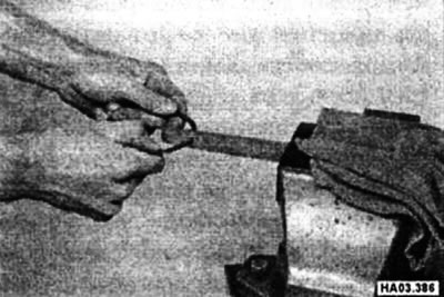
- If the gap is too small, it needs to be increased, otherwise the ends of the rings may touch each other while the engine is running, which can cause serious damage. The gap can be increased by carefully filing the ends of the rings with a fine file. Clamp the file in a vice and slowly move the ends of the rings over the file so that the metal is removed from the outside in. Filing is done at right angles and all burrs must be removed before assembly.
(Information copied from the portal: NISSANBOOK.RU)
- Repeat the described procedure for all remaining rings.
- After checking the clearance between the ring ends, the rings can be installed on the pistons using a fixture.
Tool for installing/removing piston rings
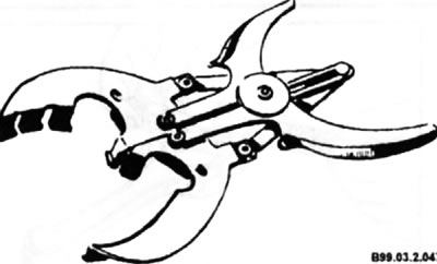
- Usually the oil scraper ring is installed first (the very bottom).
♦ Install the oil scraper ring expander (1) into the piston groove.
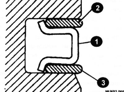
♦ Install the upper ring (2) of the oil scraper ring.
♦ Install the lower ring (3) of the oil scraper ring.
Note: No tool is required to install the oil scraper ring components.
Caution: If an old oil scraper ring is installed, the ring components must be thoroughly cleaned.
- After the oil control ring is installed, make sure that the ring rotates easily in the groove.
- Next, the second compression ring (middle) is installed.
Note: Do not confuse the top and middle rings - they have different cross-sections.
Correct positioning of rings in piston grooves
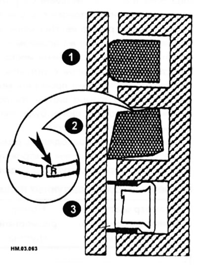
1 - upper compression ring; 2 - lower compression ring; 3 — oil scraper ring.
Note: The stamped "R" (arrow) mark on the second ring must be at the top.
- Using a ring installer, insert the ring into the middle groove of the piston. Do not open the ring more than necessary to allow the piston to pass through it.
- The top (first) ring is installed in the same way.
A simplified method for installing piston rings
- Make sure the piston ring grooves and oil passages are thoroughly cleaned. Always install rings starting from the top of the piston.
- The easiest method for installing rings is to use a flat feeler gauge (0.3-0.5 mm thick). The feeler gauge is pressed against the piston and the ring slides along it.
- Position the piston ring joints so that they are equally spaced around the circumference of the piston.
- Place the lock (2) of the oil scraper ring expander perpendicular to the axis line of the piston pin (1) on the side of the "front" mark of the piston, move the locks of the upper (4) and lower (3) oil scraper rings 45° to the right and left of the lock of the oil scraper ring expander. Move the lock of the upper compression ring (6) clockwise by 90° from the lock of the lower oil scraper ring (3), and the lock of the upper compression ring (5) by 90° counterclockwise from the lock of the upper oil scraper ring (4) so that the locks of the compression rings are opposite the locks of the oil scraper rings.
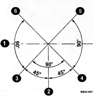
1 — piston pin axis line; 2 — line of the oil scraper ring expander lock location; 3 — location line of the lower oil scraper ring lock; 4 — line of the location of the upper oil scraper ring lock; 5 — location line of the upper compression ring lock; 6 — location line of the lower compression ring lock.