


- Regardless of how the bearing size was determined, to determine the clearance size, use plastic to measure the clearance.
- Clean the backs of the new main bearing inserts and place the halves with the oil hole on the main bearing seats in the cylinder block.
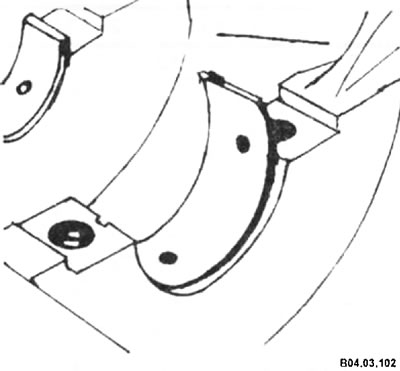
- Install the other halves from each set into the corresponding bearing caps. Make sure that the key of each bearing fits into the cutout in the cylinder block or cover.
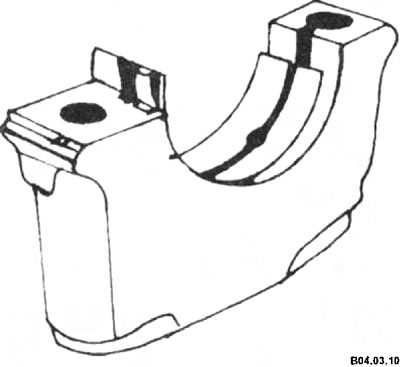
Caution: Do not hammer the bearings or scratch the bearing faces. No lubrication is required yet.
- Install the thrust bearings as follows:
♦ Install the upper thrust bearings (with a protrusion at one end) into the cylinder block on both sides of the housing for journal No. 3;
♦ Install the lower thrust bearings (with a protrusion in the center) into the main bearing cap No. 3.
Caution: Thrust bearings must be installed with the oil grooves facing the crankshaft, not the bearing shell.
- Wipe the bearing seating surfaces in the block and the crankshaft main journals with a clean cloth. Check or clean the oil holes in the crankshaft.
- Carefully place the crankshaft on the main bearings. Before final installation of the crankshaft, it is necessary to check the oil clearance of the main bearings, which is determined by simply measuring the seat diameters or using a special measuring plastic.
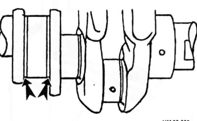
- Cut off several pieces of plastic of suitable size to measure the gap (they should be slightly shorter than the width of the main bearings) and place one piece on each main journal of the shaft parallel to its axis (arrow).
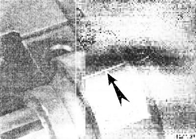
- Clean the bearing surfaces in the caps and install the caps in their places. Do not move the plastic.
- Install the covers and their support in their places so that the numbers on the covers correspond to the NS-measures of the crankshaft journals; the "front" mark on both the covers and the support is directed forward (towards the camshaft drive).
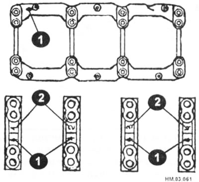
1 - "before" mark; 2 — cover number.
- Apply a thin coat of oil to the threads and underside of the bolt heads, then install them.
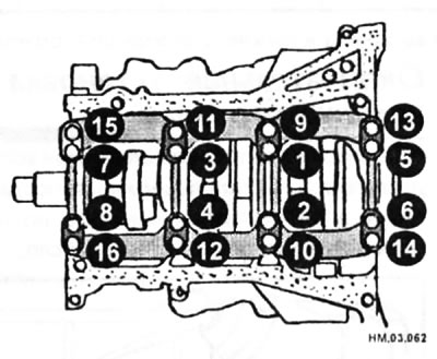
- Tighten all main bearing cap bolts in three stages to 32.3-38.3 N·m in the order shown in the illustration, then tighten another 90-95°.
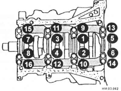
Caution: Do not turn the crankshaft during this operation.
- Loosen the bolts and carefully remove the bearing caps.
- Compare the width of the crushed plastic on each neck to the scale printed on the bag of plastic and determine the gap. Standard value is -0.04+0.005 mm. Limit value is -0.065 mm.
Attention: The plastic bag has scales in mm and inches, do not confuse them.
- If the gap is not within the norm, the bearing shells may be the wrong size. Before deciding to replace the bearings, check to see if any dirt or oil has gotten between the bearing and the cover. If one end of the gap measuring plastic is significantly wider than the other, the neck may be tapered.
- Carefully clean all traces of clearance measuring plastic from journals and bearings. Do not scratch the bearing surfaces.
- The size group of main bearing shells is selected according to the marks on the crankshaft and cylinder block.
Cylinder block identification marks
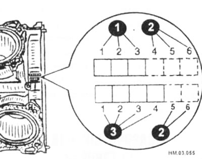
1 — cylinder bore group number; 2 — manufacturer code; 3 — insert group number.
Crankshaft identification marks
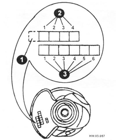
1 - identification code; 2 — number (mark) of the main journal diameter group; 3 — number (mark) of the crank pin diameter group.
Caution: After removing the main bearing caps, pay attention to the bearing shells (the size of their protrusion) (arrow) If the bearings do not protrude, then the bearings must be replaced.
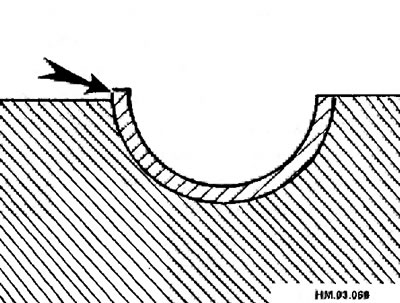
Selection of the size group of main bearing shells
| Crankshaft mark/Cylinder block mark | A | IN | WITH | D | E | F | G | N | J | TO | L | M | N | R | R | S | T | U | V | W | X | Y | 4 | 7 |
| 1 | 2 | 3 | 4 | 5 | 6 | 7 | 8 | 9 | 10 | 11 | 12 | 13 | 14 | 15 | 16 | 17 | 18 | 19 | 20 | 21 | 22 | 23 | 24 | 25 |
| A | 0 | 0 | 0 | 01 | 01 | 01 | 1 | 1 | 1 | 12 | 12 | 12 | 2 | 2 | 2 | 23 | 23 | 23 | 3 | 3 | 3 | 34 | 34 | 34 |
| IN | 0 | 0 | 01 | 01 | 01 | 1 | 1 | 1 | 12 | 12 | 12 | 2 | 2 | 2 | 23 | 23 | 23 | 3 | 3 | 3 | 34 | 34 | 34 | 4 |
| WITH | 0 | 01 | 01 | 01 | 1 | 1 | 1 | 12 | 12 | 12 | 2 | 2 | 2 | 23 | 23 | 23 | 3 | 3 | 3 | 34 | 34 | 34 | 4 | 4 |
| D | 01 | 01 | 01 | 1 | 1 | 1 | 12 | 12 | 12 | 2 | 2 | 2 | 23 | 23 | 23 | 3 | 3 | 3 | 34 | 34 | 34 | 4 | 4 | 4 |
| E | 01 | 01 | 1 | 1 | 1 | 12 | 12 | 12 | 2 | 2 | 2 | 23 | 23 | 23 | 3 | 3 | 3 | 34 | 34 | 34 | 4 | 4 | 4 | 45 |
| F | 01 | 1 | 1 | 1 | 12 | 12 | 12 | 2 | 2 | 2 | 23 | 23 | 23 | 3 | 3 | 3 | 34 | 34 | 34 | 4 | 4 | 4 | 45 | 45 |
| G | 1 | 1 | 1 | 12 | 12 | 12 | 2 | 2 | 2 | 23 | 23 | 23 | 3 | 3 | 3 | 34 | 34 | 34 | 4 | 4 | 4 | 45 | 45 | 45 |
| N | 1 | 1 | 12 | 12 | 12 | 2 | 2 | 2 | 23 | 23 | 23 | 3 | 3 | 3 | 34 | 34 | 34 | 4 | 4 | 4 | 45 | 45 | 45 | 5 |
| J | 1 | 12 | 12 | 12 | 2 | 2 | 2 | 23 | 23 | 23 | 3 | 3 | 3 | 34 | 34 | 34 | 4 | 4 | 4 | 45 | 45 | 45 | 5 | 5 |
| TO | 12 | 12 | 12 | 2 | 2 | 2 | 23 | 23 | 23 | 3 | 3 | 3 | 34 | 34 | 34 | 4 | 4 | 4 | 45 | 45 | 45 | 5 | 5 | 5 |
| L | 12 | 12 | 2 | 2 | 2 | 23 | 23 | 23 | 3 | 3. | 3 | 34 | 34 | 34 | 4 | 4 | 4 | 45 | 45 | 45 | 5 | 5 | 5 | 56 |
| M | 12 | 2 | 2 | 2 | 23 | 23 | 23 | 3 | 3 | 3 | 34 | 34 | 34 | 4 | 4 | 4 | 45 | 45 | 45 | 5 | 5 | 5 | 56 | 56 |
| N | 2 | 2 | 2 | 23 | 23 | 23 | 3 | 3 | 3 | 34 | 34 | 34 | 4 | 4 | 4 | 45 | 45 | 45 | 5 | 5 | 5 | 56 | 56 | 56 |
| R | 2 | 2 | 23 | 23 | 23 | 3 | 3 | 3 | 34 | 34 | 34 | 4 | 4 | 4 | 45 | 45 | 45 | 5 | 5 | 5 | 56 | 56 | 56 | 6 |
| R | 2 | 23 | 23 | 23 | 3 | 3 | 3 | 34 | 34 | 34 | 4 | 4 | 4 | 45 | 45 | 45 | 5 | 5 | 5 | 56 | 56 | 56 | 6 | 6 |
| S | 23 | 23 | 23 | 3 | 3 | 3 | 34 | 34 | 34 | 4 | 4 | 4 | 45 | 45 | 45 | 5 | 5 | 5 | 56 | 56 | 56 | 6 | 6 | 6 |
| T | 23 | 23 | 3 | 3 | 3 | 34 | 34 | 34 | 4 | 4 | 4 | 45 | 45 | 45 | 5 | 5 | 5 | 56 | 56 | 56 | 6 | 6 | 6 | 67 |
| U | 23 | 3 | 3 | 3 | 34 | 34 | 34 | 4 | 4 | 4 | 45 | 45 | 45 | 5 | 5 | 5 | 56 | 56 | 56 | 6 | 6 | 6 | 67 | 67 |
| V | 3 | 3 | 3 | 34 | 34 | 34 | 4 | 4 | 4 | 45 | 45 | 45 | 5' | 5 | 5 | 56 | 56 | 56 | 6 | 6 | 6 | 67 | 67 | 67 |
| W | 3 | 3 | 34 | 34 | 34 | 4 | 4 | 4 | 45 | 45 | 45 | 5 | 5 | 5 | 56 | 56 | 56 | 6 | 6 | 6 | 67 | 67 | 67 | 7 |
| X | 3 | 34 | 34 | 34 | 4 | 4 | 4 | 45 | 45 | 45 | 5 | 5 | 5 | 56 | 56 | 56 | 6 | 6 | 6 | 67 | 67 | 67 | 7 | 7 |
| Y | 34 | 34 | 34 | 4 | 4 | 4 | 45 | 45 | 45 | 5 | 5 | 5 | 56 | 56 | 56 | 6 | 6 | 6 | 67 | 67 | 67 | 7 | 7 | 7 |
| 4 | 34 | 34 | 4 | 4 | 4 | 45 | 45 | 45 | 5 | 5 | 5 | 56 | 56 | 56 | 6 | 6 | 6 | 67 | 67 | 67 | 7 | 7 | 7 | 7 |
| 7 | 34 | 4 | 4 | 4 | 45 | 45 | 45 | 5 | 5 | 5 | 56 | 56 | 56 | 6 | 6 | 6 | 67 | 67 | 67 | 7 | 7 | 7 | 7 | 7 |
The full article is available on the resource (nissanbook.ru)
Dimensions of holes in the cylinder block and crankshaft journals for main bearings and their markings
| Label | Crankshaft journal diameter | The diameter of the hole in the cylinder block for the main bearing |
| A | 59.975 - 59.974 | 63.993 - 63.994 |
| IN | 59.974 - 59.973 | 63.994 - 63.995 |
| WITH | 59.973 - 59.972 | 63.995 - 63.996 |
| D | 59.972 - 59.971 | 63.996 - 63.997 |
| E | 59.971 - 59.970 | 63.997 - 63.998 |
| F | 59.970 -59.969 | 63.998 - 63.999 |
| G | 59.969 - 59.968 | 63.999 - 64,000 |
| N | 59.968 - 59.967 | 64.000 - 64.001 |
| J | 59.967 - 59.966 | 64.001 - 64.002 |
| TO | 59.966 - 59.965 | 64.002 - 64.003 |
| L | 59.965 - 59.964 | 64.003 - 64.004 |
| M | 59.964 - 59.963 | 64.004 - 64.005 |
| N | 59.963 - 59.962 | 64.005 - 64.006 |
| R | 59.962 - 59.961 | 64.006 - 64.007 |
| R | 59.961 - 59.960 | 64.007 - 64.008 |
| S | 59.960- 59.961 | 64.008 - 64.009 |
| T | 59.959 - 59.958 | 64.009- 64.010 |
| U | 59.958 - 59.957 | 64.010- 64.011 |
| V | 59.957 - 59.956 | 64.011 -64.012 |
| W | 59.956 - 59.955 | 64.012 - 64.013 |
| X | 59.955 - 59.954 | 64.013- 64.014 |
| Y | 59.954 - 59.953 | 64.014-64.015 |
| 4 | 59.953-59.952 | 64.015-64.016 |
| 7 | 59.952 - 59.951 | 64.016- 64.017 |
Dimensional groups of main bearing shells
| Size group number | Thickness | Width | Ident color (upper/lower) | |
| 0 | 2,000-2,003 mm | 19.9-20.1 mm | Black | |
| 1 | 2.003-2.006 mm | Brown | ||
| 2 | 2.006-2.009 mm | Green | ||
| 3 | 2.009-2.012 mm | Yellow | ||
| 4 | 2.012-2.015 mm | Blue | ||
| 5 | 2.015-2.018 mm | Pink | ||
| 6 | 2.018-2.021 mm | Violet | ||
| 7 | 2.021-2.024 mm | White | ||
| 01* | Upper | 2.003-2.006 mm | Brown/black | |
| Lower | 2,000-2,003 mm | |||
| 12* | Upper | 2.006-2.009 mm | Green/brown | |
| Lower | 2.003-2.006 mm | |||
| 23* | Upper | 2.009-2.012 mm | Yellow/green | |
| Lower | 2.006-2.009 mm | |||
| 34* | Upper | 2.012-2.015 mm | Blue/yellow | |
| Lower | 2.009-2.012 mm | |||
| 45* | Upper | 2.015-2.018 mm | Pink/blue | |
| Lower | 2.012-2.015 mm | |||
| 56* | Upper | 2.018-2.021 mm | Purple/pink | |
| Lower | 2.015-2.018 mm | |||
| 67* | Upper | 2.021-2.024 mm | White/purple | |
| Lower | 2.018-2.021 mm | |||
*the size groups of the upper and lower liners are different.
- If the required oil clearance cannot be achieved using standard size main bearing shells, oversize shells must be used.
- When using oversize main bearing shells, measure the inside diameter of the shells in the installed state and regrind the crankshaft main journal so that the oil clearance value corresponds to the standard values.
| Size, mm | Thickness, mm |
| Repair size 0.25 | 2,132-2,140 |
Attention: When regrinding the crankshaft main journals for oversize liners, it is necessary to maintain a flange (arrows) on all crankshaft journals of 1.5 mm in size.
Final installation of the crankshaft
- Carefully pull the crankshaft out of the engine. Clean the bearing surfaces in the block, then apply a uniform layer of engine oil to them.
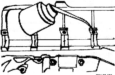
- Lubricate the crankshaft surfaces in contact with the seals with clean engine oil.
- Make sure the crankshaft journals are clean, then place the shaft back in the cylinder block.
- Clean the bearing surfaces in the caps and apply grease to them.
- Install the covers and their support in their places so that the numbers on the covers correspond to the numbers on the crankshaft journals, and the "front" mark on both the covers and the support is directed forward (towards the camshaft drive).
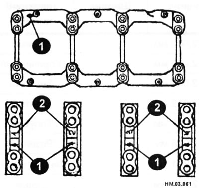
1 — "front" mark: 2 — cover number.
Caution: Before final installation of the crankshaft, it is necessary to measure the diameters of the main bearing cap bolts in two places, at a distance of 10 and 40 mm from the start of the thread at the end of the bolt. If the difference in diameters is more than 0.11 mm, then such a bolt must be replaced.
- Apply a thin coat of oil to the threads and underside of the bolt heads, then install them.
- Tighten all main bearing cap bolts in three stages to 32.3-38.3 N·m in the order shown in the illustration, then tighten another 90-95°.
- Measure the shaft play using feeler gauges or an indicator (see above).
- Turn the crankshaft by hand several times and check if it is jamming.
- Install the rear oil seal with the holder
- Install the guide bushing with the beveled side towards the crankshaft using a drift.