


- Before checking, the pistons and connecting rods must be cleaned and the old rings removed from the pistons.
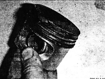
Caution: Install new piston rings whenever the engine is disassembled.
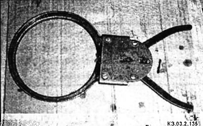
- Using a ring installer, carefully remove the old rings from the pistons. Be careful not to scratch or damage the pistons in the process.
- Clean all traces of carbon (fouling) from the top of the piston using a hand wire brush or sandpaper. If there is heavy carbon deposits, you can use a piece of an old piston ring.
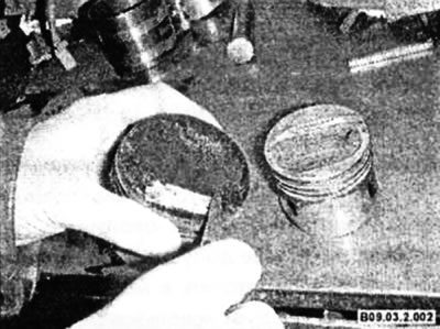
- Never use a wire brush attached to a drill, as it may damage the piston, which is made of a soft material.
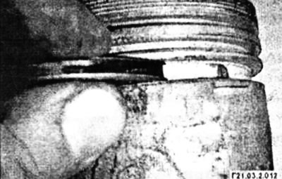
- Using a piece of an old piston ring, clean away any carbon deposits in the ring grooves. Clean off only the carbon deposits and do not remove metal or scratch the sides of the grooves.
- After you have cleaned off the carbon deposits, clean the pistons and connecting rods with solvent and dry them. Make sure the oil return holes in the sides of the ring grooves are clean.
- If the pistons and cylinder walls are not too worn or damaged, and if the cylinders have not been bored, old pistons can be used. Normal piston wear appears as vertical wear stripes on the piston bearing surfaces and a slight looseness of the top ring in its groove.
- Check for burrs or scratches on the bearing surfaces of the skirt, in the piston pin bore, or any burned areas on the edge of the head.
- If the skirt is scratched or worn, the engine may suffer from overheating and/or abnormal combustion, resulting in excessively high operating temperatures. Such pistons should be replaced. Lubrication and cooling systems must be carefully checked. A hole in the piston head indicates abnormal combustion (premature (early) ignition). Burnt areas on the edge of the head usually indicate detonation. If any of the above problems occur, their causes must be eliminated, otherwise the damage will reoccur. Causes may include intake air leaks, incorrect air-fuel mixture, incorrect ignition timing, and improper operation of the exhaust gas recirculation system.
A typical burnt piston resulting from abnormal combustion
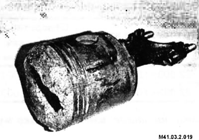
- Piston corrosion in the form of small pits indicates that coolant is leaking into the combustion chamber and/or crankcase. This problem must also be corrected.
- Measure the piston ring side clearance by placing a new ring (2) in each groove and inserting a feeler gauge (1) next to it. Measure the clearance at three or four points along the diameter of each groove. Make sure you use the correct ring - they are different. If the side clearance is greater than the permissible limit, the piston must be replaced.
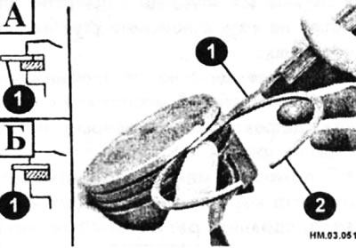
Attention: The feeler gauge must be inserted all the way into the piston, as shown in Figure HM03-051, Part B; Part A shows the incorrect position of the feeler gauge.
Nominal value:
Upper compression ring: 0.045-0.080 mm.
Second compression ring: 0.030-0.070 mm.
Oil scraper ring: 0.065-0.135 mm.
Maximum permissible value:
Upper compression ring: 0.11 mm.
Second compression ring: 0.1 mm.
- Check the clearance between the piston and the cylinder wall by measuring the cylinder bore diameter and the piston diameter. Measure the piston diameter across the skirt, coaxially and at an angle of 90° to the piston pin. The clearance is defined as the difference between the diameters of the cylinder bore and the piston. If the clearance is greater than the permissible limit, the cylinder bores should be reamed and new pistons and rings should be used.
- Check the side clearance between the piston and connecting rod by moving them in opposite directions. Any noticeable play indicates that there is excess wear that needs to be corrected. The piston, together with the connecting rod, should be machined and new rings of the repair size installed.
(The article was obtained from the portal: NissanBook.ru)
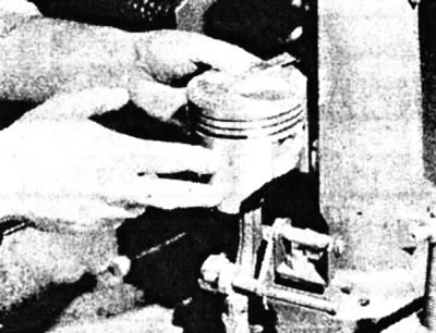
- Check the crank arms for bending and twisting of the rod. The bending of the connecting rod in the plane of the crankshaft axis and twisting must not exceed the permissible values. These defects are determined in the workshop using a device.
- The maximum permissible bending value is 0.15 mm per 100 mm of connecting rod length and twisting is 0.30 mm per 100 mm of connecting rod length.
- A connecting rod with a bend and twist greater than the permissible limit can be straightened without heating using a special lever with a jaw and a clamp.
Caution: To avoid damaging the heads, grasp the connecting rod being straightened by the T-section.
- Bend the connecting rod in the opposite direction, and then straighten it to the required position. Then it is necessary to thermally stabilize the connecting rod by heating it to 400-450°C and holding it at this temperature for 1.5-2 hours.
Note: It is best to replace such a connecting rod with a new one, selected according to weight. The difference in weight between the old and new connecting rods should not exceed 4.0 g.
- Remove the connecting rod pin retaining rings.
- Heat the piston with a hair dryer or in a container with oil to a temperature of 60-70°C.
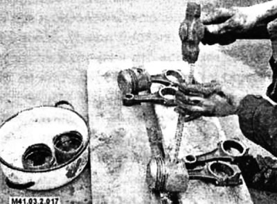
- Place the piston and connecting rod assembly on a jig or wooden blocks and press out the pin with a suitable wooden block.
Typical piston pin pressing at home
- Clean and wash the removed parts.
- Check the connecting rods for cracks or other damage (arrow).
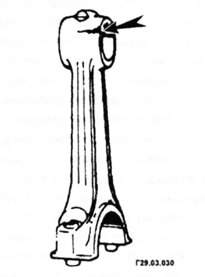
- Check the connecting rod bushing oil clearance by measuring the connecting rod small end bore diameter and the piston pin diameter.
- The standard value should be 0.011 ±0.006 mm, and the maximum permissible value is 0.030 mm.
- If the gap is greater than the maximum permissible value, the entire piston and connecting rod assembly must be replaced.
Dimensional groups of piston pin-connecting rod-piston mating parts
| Group number | Outer diameter of piston pin, mm | Connecting rod upper head bushing bore diameter, mm | Piston boss bore, mm |
| 0 | 21,992±0,003 | 22,003+0,003 | 21,996+0,003 |
| 1 | 21,998±0,003 | 22,009+0,003 | 22,002±0,003 |
Please note: Factory installed parts are of group zero only.
Connecting rod identification marks
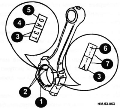
1 - "before" mark; 2 - locking groove for connecting rod bearing shells; 3 - factory mark; 4 - mass group; 5 — the number of the group of the hole diameter in the upper head of the connecting rod; 6 — standard mark; 7 — cylinder number.
Piston identification marks
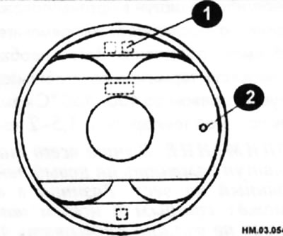
1 — piston pin outer diameter group number; 2 - "front" mark.