


2. Place the car on a flat surface, apply the handbrake, block the wheels, and put the gear in neutral.
3. Valve clearances and ignition timing must be adjusted correctly, turn off the electric cooling fan motor.
4. The idle mixture quality is set at the factory, so usually only the idle speed is adjusted.
Adjusting the idle speed
5. Warm up the engine to normal operating temperature.
6. All lights and other electrical consumers, including the air conditioning system, must be turned off.
7. Make a wiring adapter and connect as shown in Figure 4.16. Connect the tachometer.
8. Accelerate the engine to 2000 - 3000 rpm two or three times, let it idle for one minute.
9. Check the idle speed. If necessary, adjust the idle speed screw located on the back of the IAA block (Figure 3.44).
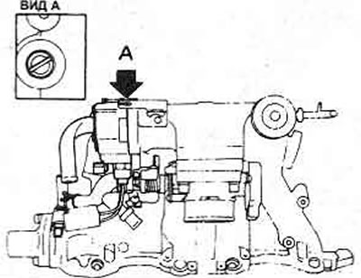
Figure 3.44. Location of the idle speed adjustment screw
FICD speed control
10. Check the idle speed as described above.
11. Turn on the air conditioning system and measure the increase in idle speed. If adjustment is required, turn the FICD adjusting screw on the right side of the 1AA block (Figure 3.45).
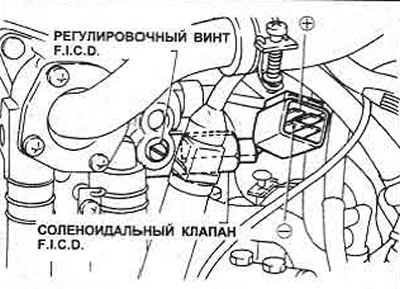
Figure 3.45. FICD Parts Location - Executive Model
12. If the idle speed does not increase, stop the engine, disconnect the FICD valve wiring. Connect the battery to the clamp wires; listen for clicking sounds in the valve. If the valve is faulty, replace it. Adjusting the idle mixture
13. If the mixture has been adjusted due to changes in engine characteristics (carbon deposits, wear of cylinder bores, etc.), first adjust the idle speed, then stop the engine.
14. The quality of the mixture must be checked using a CO meter (exhaust gas analyzer). You will need an accurate tachometer and a 2.5 kOhm resistor.
15. Before checking the idle mixture, first warm up the engine to normal operating temperature and check the valve clearances, ignition timing and idle speed as described above.
16. Connect the CO meter according to the manufacturer's instructions, and check the CO level at idle speed. If adjustment is required, proceed as follows.
17. Remove the rubber cap from the mixture adjustment screw, carefully drill a small hole in the aluminum plug, and remove it (Figure 3.46).
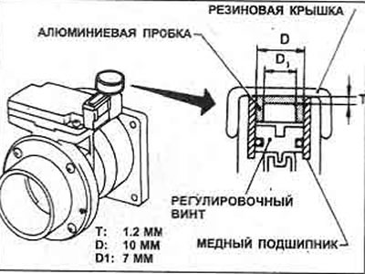
Figure 3.46. Idle mixture adjustment screw plug parts
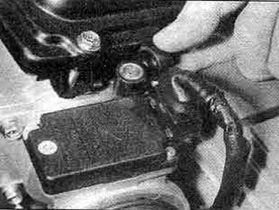
41.17. Idle mixture adjusting screw under the plug in the air flow meter
18. Disconnect the wires from the coolant temperature sensor, connect a 2.5 kOhm resistor to the connector terminals (Figure 3.47).
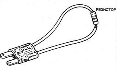
Figure 3.47. 2.5 kOhm resistor and idle mixture adjustment adapter harness
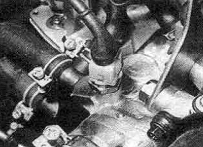
41.18A. Disconnect the wiring from the water temperature sensor...
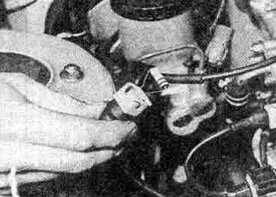
41.18B.... and install a resistor when adjusting the idle mixture
19. Warm up the engine to normal operating temperature. Check the CO level.
20. The CO level should increase gradually, as the injection system produces a rich mixture for starting and warming up.
21. Turning the mixture adjusting screw (which is actually a variable resistor), set the CO level to less than 8%. Turn off the engine, remove the resistor, connect the water temperature sensor.
22. Start the engine, check the CO level and idle speed. Stop the engine, disconnect the test equipment, install the rubber cap. Connect the electric cooling fan motor.
23. To adjust the idle mixture without a CO meter, first connect an accurate tachometer (item 7) and prepare the car as described in item 15 above.
24. Stop the engine, remove the plug from the air flow meter, then insert the 2.5 kΩ resistor as described in steps 17 and 18 above. Start the engine, bleed excess fuel from the intake manifold as described in step 8 above.
25. Gently turn the idle mixture adjusting screw in each direction until the fastest idle speed is obtained, then stop the engine, remove the resistor and reconnect the water temperature sensor.
26. Start the engine and remove excess fuel from the intake manifold (item 8), then check the idle speed and reduce it, if necessary, to the specified value using the idle speed adjusting screw (item 9).
27. Stop the engine, disconnect the electric cooling fan motor. Do not install a new plug until you have checked the mixture with a CO meter.
Adjusting the dashpot
28. Warm up the engine to normal operating temperature.
29. With the engine idling, open the throttle pulley until the lever rests on the dashpot plunger. Note (dashpot contact) engine speed at this point (photo).
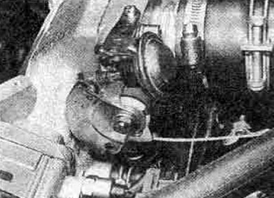
41.29. Throttle Pulley/Lever and Dashpot
30. If adjustment is required, turn the throttle lever adjusting screw.
Adjusting the Throttle Valve Switch
31. The switch must be adjusted so that the contacts open at 900±250 rpm.
32. Connect an accurate tachometer to the engine (the adapter is shown in Figure 4.16).
33. Release the wiring harness retaining clip securing the throttle switch connector. Start the engine.
34. Loosen the switch mounting bolts, keeping the engine running in fast idle mode, connect a multimeter to the switch terminals in resistance measurement mode (or a battery with a lamp).
35. The circuit on the switch terminals (29 and 30) should be closed when the throttle valve is closed. When the valve opens slightly, the contacts should open. If faulty, replace the switch.
36. Set the engine speed to 950±250 rpm by slowly rotating the switch from closed to open position. Fix this position and tighten the bolts.
37. Check the installation before stopping the engine, disconnect the test equipment and restore the switch wiring connections.