General diagnostics
1. If a malfunction occurs in the fuel injection / ignition system, first check that all system connections are securely connected and not corroded.
2. Then check to see if poor engine maintenance is the cause of the problem; i.e., check that the air filter element is not clogged, that the spark plugs are in good condition and have the correct spark gap, that the engine valve clearances are correctly adjusted and that the compression pressure in the cylinders is at the required value.
3. Also check that the ignition timing is set correctly and that the emission control systems are working properly. See subsection 7.7.1 Andsubsection 6.4 for more detailed information.
4. If these checks fail to locate the source of the problem, a quick test of the fuel injection/ignition circuits can be performed by placing the engine control module in self-diagnostic mode "2".
5. In mode "2" the electronic control unit will show the fault code stored in its memory by turning on the warning light on the instrument panel or the red LED on the right side of the control unit.
6. Records of malfunctions detected by the electronic control unit are stored in its memory until the starter is turned on 50 times.
7. If the fault is not detected again within this period of time, the record of it will be erased from memory.
8. Fault records can be erased from the memory of the electronic control unit by turning it into self-diagnosis mode "2", and then switching back to "1" or by disconnecting the battery for more than 24 hours.
Setting the self-diagnosis modes
1. Remove the fuse box cover to gain access to the diagnostic connector, which is attached to the bottom of the fuse box.
2. Turn the ignition key to position "ON", but do not start the engine. The ECM is now in self-diagnosis mode "1".
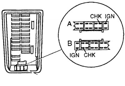
3. Using a piece of wire, connect the terminal "IGN" diagnostic connector and terminal "CHK".
4. Keep the terminals connected for more than 2 seconds, then disconnect the wire. The ECM is now in self-diagnosis mode "2".
5. In mode "2" the electronic control unit will show the fault code recorded in its memory.
Attention! If codes 11 and 21 are displayed at the same time, check the crank angle sensor circuit before checking the rest of the ignition system.
6. On models with a catalytic converter, if the electronic control unit is set to "2", when the engine is started, the electronic control unit automatically enters the exhaust gas sensor test mode. In this mode, the warning light on the instrument panel and the red LED indicate the status of the exhaust gases. When the warning light and LED are on, it means that the exhaust gases are low in CO, and when they are off, it means that the exhaust gases are saturated with CO.
7. To check the sensor, put the electronic control unit in self-diagnosis mode "2", start the engine and warm it up to normal operating temperature.
8. After the engine is warm, raise the engine speed to about 2000 rpm and hold this speed for about 2 minutes, watching the warning light on the instrument panel or the LED on the electronic control unit.
9. If the exhaust gas sensor is working properly, the warning light/LED should flash at least 5 times every 10 seconds.
10. After completing all checks, exit the self-diagnostic mode "2".
11. If you did not start the engine, from the self-diagnosis mode "2" can be exited by reconnecting the terminals "IGN" And "SNK" diagnostic connector for more than 2 seconds.
12. If the engine is running, exit the self-diagnostic mode "2", by turning the key in the ignition switch to position "OFF" and disconnect the negative battery cable.
13. If it is necessary to carry out a more detailed check of the fuel injection / ignition system, contact specialists. The repair shop must have an electronic diagnostic tool that connects to the diagnostic socket and allows a complete check of all elements of the system.
Adjustment
On models without a catalytic converter, the idle speed and fuel mixture can be adjusted (CO level in exhaust gases). On models with a catalytic converter, only idle speed can be adjusted.
Fault codes
| Code | Faulty circuit |
| 11 | Crank Angle Sensor Circuit |
| 12 | Air flow sensor circuit |
| 13 | Coolant temperature sensor circuit |
| 21 | Ignition signal circuit |
| 34 | Fuel Knock Sensor Circuit |
| 43 | Throttle Potentiometer Circuit |
| 55 | All circuits are working properly |