


Disassembly
1. Before removing parts from the input shaft, measure the axial clearance of the 5th gear pinion (see section "Data for adjustments and control"). If it is not within the specified limits, disassemble the shaft and check the contact surfaces of the gear, shaft and hub of the synchronizer clutch. Then check the clearance between the retaining ring and the groove (see subsection "Assembly").
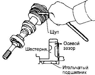
2. Remove the 5th gear retaining ring and thrust washer.
3. Remove the synchronizer, pinion gear and 5th gear needle bearing using the special tool.
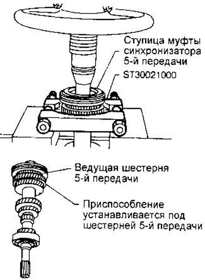
4. Remove the front input shaft bearing retaining ring and spacer ring.
5. Press out the front bearing of the input shaft.
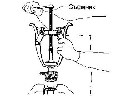
6. Remove the bearing holder.
Examination
Shaft with gears. Check for cracks, visible wear, and shaft bending. There should be no chips, cracks, or wear marks on the gear teeth.
Synchronizer. Check the splined parts of the clutch, synchronizer hub and gear for cracks or wear. The locking rings should not be worn or deformed. Also make sure that the crackers are not worn or deformed.
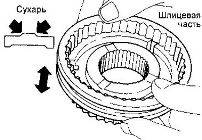
Measure the gap between the locking ring and the gear ring:
- Nominal clearance - 1.0-1.35 mm
- Maximum permissible - 0.7 mm
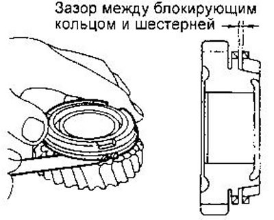
Bearings. Make sure that the bearings rotate freely, without extraneous noise, and are free of cracks, pitting, and visible wear.
Assembly
1. Assemble the 5th gear synchronizer. Note that the ends of the return springs must engage different crackers.
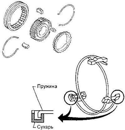
2. Install the bearing retainer.
3. Press the front bearing onto the input shaft using the ST22350000 drift.
4. Put on the spacer ring.
5. Select and install a retaining ring that fits into the shaft groove with a clearance of 0-0.1 mm. Available ring thicknesses are listed in the section "Data for adjustments and control".
6. Install the needle bearing, pinion, synchronizer and 5th gear thrust washer. Use the ST37750000 mandrel to press on the synchronizer clutch hub.
7. Check the axial clearance of the gear (see subsection "Disassembly").
8. Select and install a retaining ring that fits into the shaft groove with a gap of 0-0.1 mm. Available thicknesses of the 5th gear synchronizer retaining rings are given in the section "Data for adjustments and control".