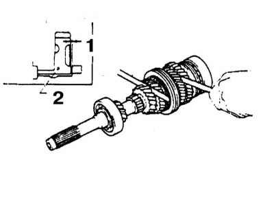
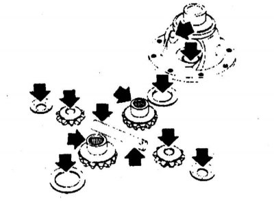
The layout of the internal components of the manual transmission
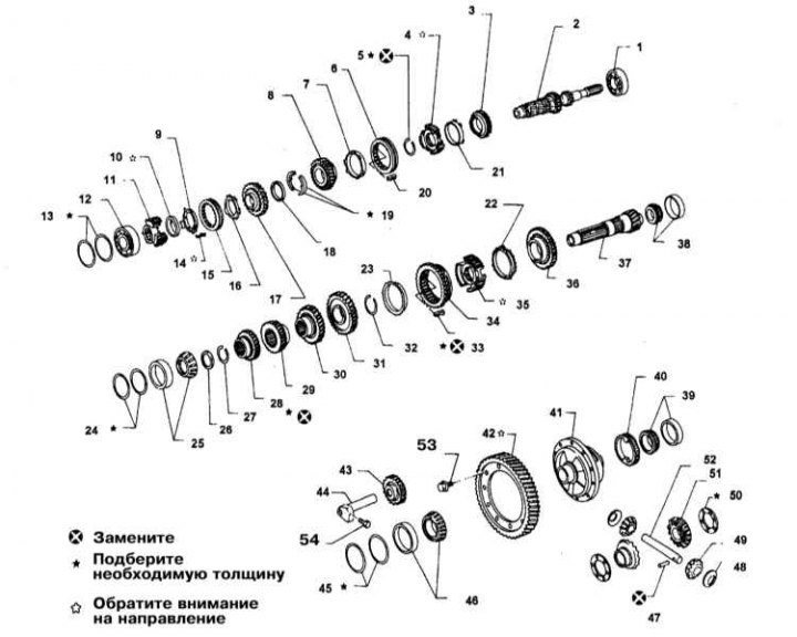
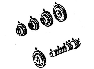
1 - Front bearing of the input shaft; 2 - Primary shaft; 3 - Drive gear 3rd gear; 4 - Hub of the sliding sleeve of the synchronizer; 5 - Thrust ring; 6 - Sliding clutch; 7 - 4th gear blocking ring; 8 - Drive gear 4th gear; 9 - Blocking ring of the reverse gear synchronizer; 10 - Cone of the reverse gear synchronizer; 11 - Hub of the sliding clutch of the synchronizer of the 5th gear; 12 - Rear bearing of the input shaft; 13 - Adjusting rings of the rear bearing of the input shaft; 14 - Spring wrench; 15 - Sliding clutch of the synchronizer; 16 - 5th gear synchronizer blocking ring; 17 - Drive gear 5th gear; 18 - Retaining ring; 19 - Thrust half rings of the input shaft; 20 - Spring wrench; 21 - Blocking ring of the reverse gear synchronizer; 22 - 1st gear synchronizer blocking ring; 23 - 2nd gear synchronizer blocking ring; 24 - Adjusting rings of the rear bearing of the secondary shaft; 25 - Rear bearing of the secondary shaft; 26 - Thrust washer; 27 - Thrust ring; 28 - Driven gear of the 5th gear; 29 - Driven gear 4th gear; 30 - Driven gear 3rd gear; 31 - Driven gear 2nd gear; 32 - Thrust ring; 33 - Spring wrench; 34 - Driven gear of the rear transmission; 35 - Synchronizer hub 1-2 gears; 36 - Driven gear 1st gear; 37 - Secondary shaft; 38 - Front bearing of the secondary shaft; 39 - Differential bearing; 40 - Speedometer drive gear; 41 - Differential box; 42 - Driven gear of the main gear; 43 - Intermediate reverse gear; 44 - Axis of the intermediate gear of the reverse gear; 45 - Adjusting rings of the bearing; 46 - Differential bearing; 47 - Pin; 48 - Thrust washer of the axis of the satellites; 49 - Differential satellite; 50 - Thrust washer of the side gear of the differential; 51 - Differential side gear; 52 - Axis of satellites; 53 - Bolt (74÷88 Nm); 54 - Bolt (16÷21 Nm)
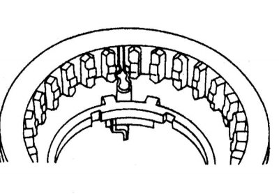
Gear Selector Components
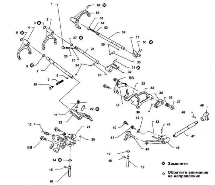
1 - Plug of the interlock of the shift fork of the 3rd and 4th gears; 2 - Fork shift 3-4 gears; 3 - Retaining ring; 4 - 5th gear engagement fork; 5 - Retaining ring; 6 - Retaining ring; 7 - 5th gear fork rod; 8 - Blocking ball; 9 - Return spring; 10 - Control plug 5th and reverse gears (16 ø 22 Nm); 11 - Retaining spring; 12 - Bracket for 5th and reverse gears; 13 - Spring level reverse gear; 14 - O-ring; 15 - Pin; 16 - Axis of the reverse lever; 17 - O-ring; 18 - Pin; 19 - Gear selection rod; 20 - Ball; 21 - Reverse enable device; 22 - Mutual blocking plunger; 23 - Ball interlock; 25 - Ball; 26 - Return spring; 27 - Retaining ring; 28 - 3-4 shift fork rod; 29 - Ball; 30 - Mutual blocking plunger; 31 - Pin; 32 - Bracket; 33 - Return spring; 34 - damper; 35 - Selector foot; 36 - Return bearing; 37 - Bushing; 38 - Selector spring; 39 - Ball; 40 - Cam pin; 41 - Return spring; 42 - Cam; 43 - Pin; 44 - Pin; 45 - Selector; 46 - Locking lever; 47 - Locking rod; 48 - Pin; 49 - Fork clamp; 50 - Pin; 51 - Bracket; 52 - 1-2 shift fork rod; 53 - Ball; 54 - Return spring; 55 - Plug of the interlock of the shift fork of 1-2 gears; 56 - Shift fork 1-2 gears; 57 - Pin; 58 - Bolt (16÷21 Nm); 59 - Bolt (16÷21 Nm)
General information
The compilers of this Guide do not recommend car owners to undertake the overhaul of manual transmissions on their own. During the disassembly and assembly procedures, the gearbox has to be removed and then replaced with many small components. It is necessary to make a lot of accurate measurements and, by selecting shims, rings and spacers, clearly set a lot of gaps. In view of the foregoing, it would be wiser to entrust the overhaul of the manual transmission to the car service specialists. Note that in many cases it is possible to purchase a refurbished unit on an exchange basis, which is often cheaper than a complex repair.
Despite the foregoing, the independent repair of the manual transmission by an amateur mechanic is not at all an absolutely impossible undertaking. Indispensable conditions are only the availability of the necessary special tools and accuracy in the approach to the implementation of all procedures.
Tools needed to rebuild manual transmissions include needle nose pliers for removing inner and outer circlips, a bearing puller, a slide hammer, a set of drifts and center punches, a DTI gauge, and possibly a hydraulic press. In addition, of course, you will need a durable, vise-equipped workbench, or a special assembly stand.
During the manual transmission disassembly procedures, try to remember, or rather write down, the installation order of each of the removed parts.
Before proceeding with the disassembly of the gearbox, it would be wise to try to analyze the symptoms of its failures in order to approximately determine their causes. Many failures are uniquely related to the failure of well-defined components.
The following subsection provides a schematic description of the procedure for disassembling the manual transmission and servicing its internal components.
Disassembly, maintenance of internal components and assembly of manual transmission
Extracting Components
1. The layout of the internal components of the manual transmission and the gear selection mechanism is shown in the illustrations.
2. Remove the 4th gear through the hole, then remove the reverse idle gear axle and the gear itself.
3. Remove the mounting pin from the coupling body.
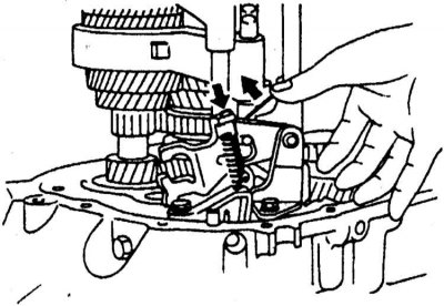
4. Remove the lever return spring and reverse detent spring from the reverse gear engagement mechanism.
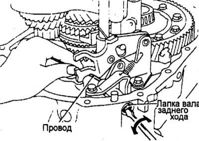
5. Remove the reverse gear axle tab.
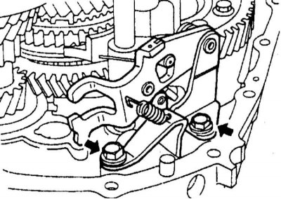
6. Remove the reverse gear lever assembly.
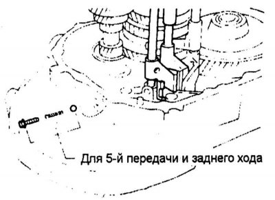
7. Remove the plug of the 5th and reverse fork interlock, remove the spring and ball.
8. Remove the circlips and mounting pins from the 5/Reverse and 3-4 shift forks.
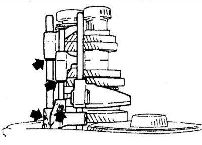
9. Remove 5/reverse and 3-4 gears.
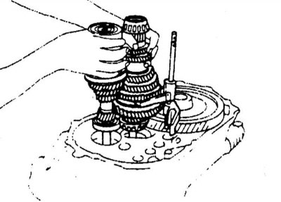
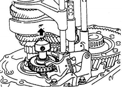
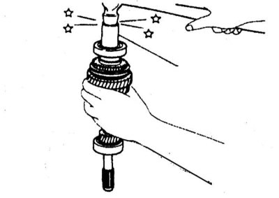
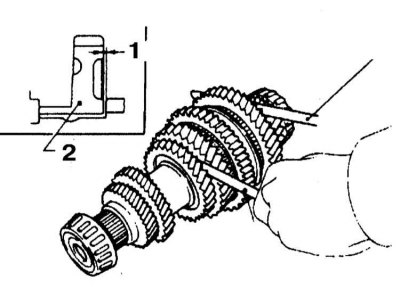
10. Remove both shaft assemblies (primary and secondary) Manual transmission and fork 1-2 gears with its stock.
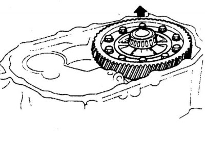
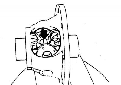
11. Remove the final drive assembly.
12. Remove the reverse gear assembly.
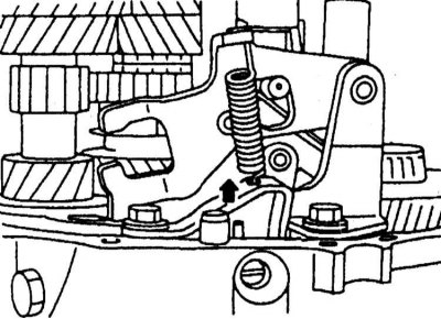
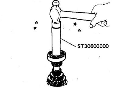
13. Using a special drift (KV32101000) remove the mounting pin and disconnect the selector.
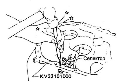
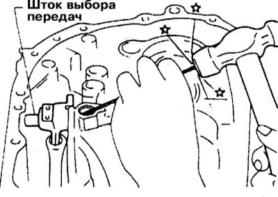
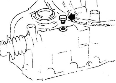
14. Turn out a drain stopper, for the purpose of providing access to a pin of fastening of the lever with a rod.
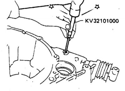
15. Remove pin (use punch KV32101000) and remove the stem lever.
Removing the input shaft assembly
Disassembly
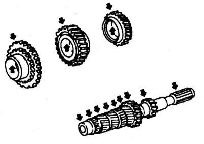
1. Before proceeding with the dismantling of the input shaft, evaluate the amount of axial play of the drive gears of the 3rd, 4th and 5th gears.
 |  |
2. If the gear play is out of range (see specs), dismantle the assembly and check the condition of the mating surfaces of the gears, shaft and hubs, then evaluate the clearance of the retaining ring and thrust semi-rings of the input shaft.
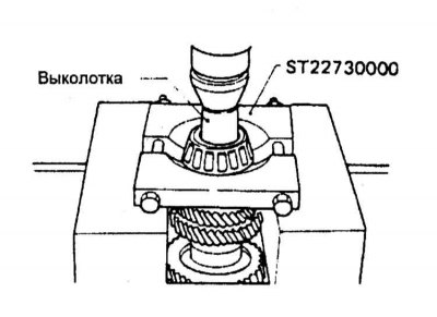
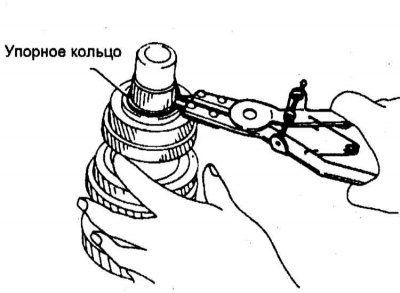
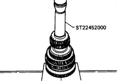
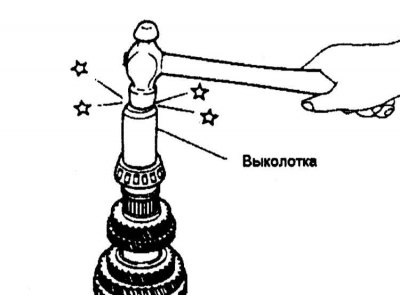
3. Remove the input shaft rear bearing.
4. Remove the 5th and reverse synchro assemblies and the 5th gear.
5. Remove the axle lock washer, the two thrust washers and the 4th gear.
6. Remove the retaining ring.
7. Remove the 3rd-4th gear synchronizer and 3rd gear pinion.
8. Remove the input shaft front bearing.
Checking the Status of Components
1. Check the input shaft assembly for cracks, signs of deformation and excessive wear, evaluate the condition of the drive gears.
2. Check synchronizer components for cracks, signs of excessive wear, cracks, and other mechanical defects. Assess the condition of the hubs, sliding sleeves, lock rings, keys, and other assembly parts.
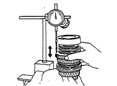
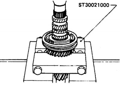
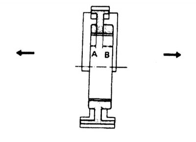
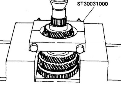
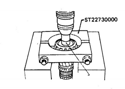
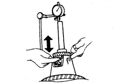
3. Measure the gap between the synchronizer blocking ring and the gear (for 4th and 5th gears). The nominal value lies within the range of 1.0÷1.35 mm with a wear tolerance of up to 0.7 mm.
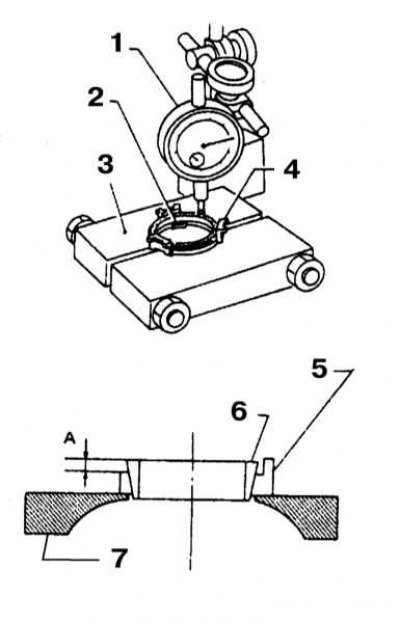
1 - Dial gauge; 2 - Synchronizer cone; 3 - Screed (fixture ST30031000); 4 - Blocking ring; 5 - Synchronizer cone; 6 - Screed (fixture ST30031000)
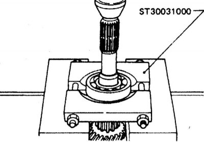
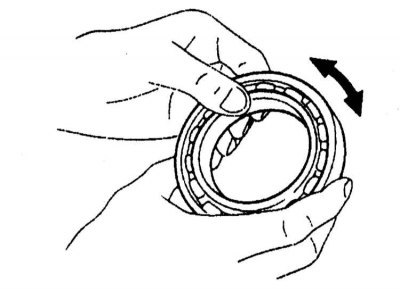
4. Estimate degree of deterioration of a blocking ring of the synchronizer of a reverse gear. Lay the blocking ring on a suitable fixture and place the synchronizer cone on it. Make sure that the projection of the cone falls within the perimeter of the recess in the fixture. While firmly pressing the cone against the blocking ring, use a plunger-type dial gauge to determine distance A. If A is less than 1.2 mm, replace the blocking ring.
5. Assess the freedom of rotation of the bearings.
6. Check bearing assemblies for cracks, cavities and other mechanical damage.
Assembly
1. Assemble the 3-4 gear synchronizer. Check that the components are correctly engaged.
2. Place the 3rd gear drive gear and the corresponding synchronizer blocking ring on the input shaft assembly.
3. Press the 3-4 gear synchronizer clutch hub onto the assembly. Make sure the components are oriented correctly. Select and install the appropriate thrust washer to minimize the gap in the groove (the gap size should not go beyond the range of 0÷0.1 mm).
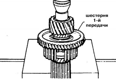
4. Install the 4th gear.
5. Select appropriate thrust washers to minimize slot clearance (0÷0.06 mm) and seat them on the thrust ring.
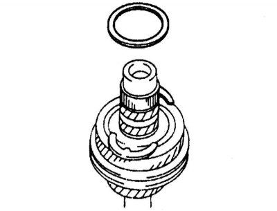
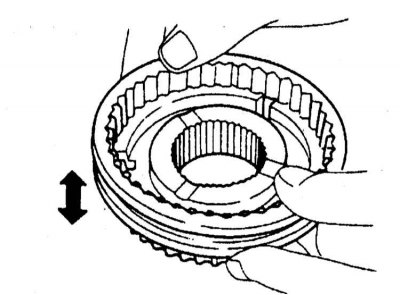
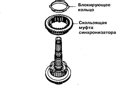
6. Establish the synchronizer of 5th and reverse gears. Insert the spring wrenches into the reverse synchro-ring. Enter the assembly into the sliding sleeve of the synchronizer, - make sure that the spring keys are inserted into the sleeve correctly.
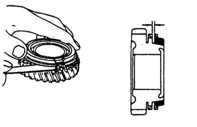
1 - 5th gear
2 - Assembling the reverse gear synchronizer
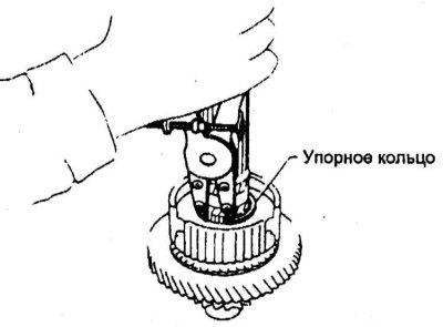
7. Fit the 5th gear blocking ring into the appropriate drive gear. Install the reverse synchro cone on your blocking ring. Place the assembled reverse gear synchronizer on the 5th gear. Insert the lugs of the cone into the reciprocal slots of the gear.
8. Position the reverse synchroniser ring circlip retainers on top of the 5th gear.
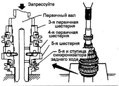
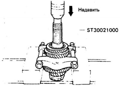
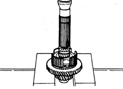
9. Press the 5th and reverse synchro assembly with the 5th gear onto the input shaft assembly.
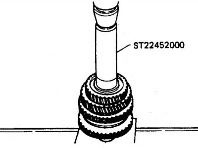
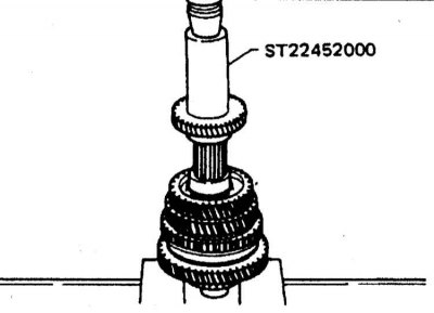
10. Place the front and rear bearings on the input shaft assembly.
 |  |
11. Estimate the amount of axial play of the gears.
Removing the output shaft assembly
Disassembly
1. Before proceeding with the dismantling of the assembly components, measure the amount of axial play of the driven gears of the 1st and 2nd gears. If the measurement results are out of range (see specs), remove the components and evaluate the condition of the mating surfaces of the shaft, gears and hubs (see subsection Assembly).
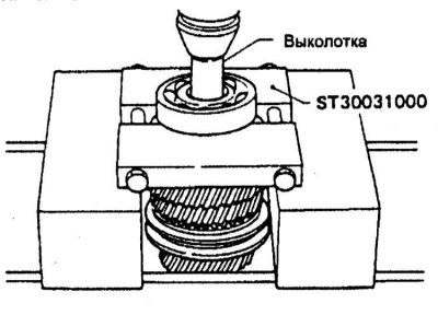
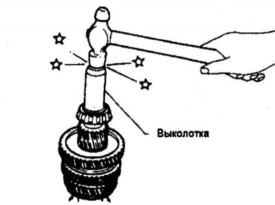
2. Press out the rear output shaft bearing.
3. Remove thrust washer and ring.
4. Press out the driven gears of the 5th and 4th gears.
5. Press out the driven gears of the 3rd and 2nd gears.
6. Remove the thrust ring.
7. Remove the 1-2 gear synchronizer assembly and 1st gear driven gear.
8. Press out the rear bearing
Checking the Status of Components
1. Check the shaft for cracks, deformations and signs of excessive wear, evaluate the condition of the gears.
2. Check synchronizer components for cracks, signs of excessive wear, cracks, and other mechanical defects. Assess the condition of the hubs, sliding sleeves, lock rings, keys, and other assembly parts.
3. Measure the gap between the synchronizer blocking ring and the gear (for 4th and 5th gears). The nominal value lies within the range of 1.0÷1.35 mm with a wear tolerance of up to 0.7 mm.
4. Assess the freedom of rotation of the bearings. Check bearing assemblies for cracks, cavities and other mechanical damage.
Assembly
1. Assemble the 1-2 gear synchronizer. Check that the components are correctly engaged.
2. Install the 1st driven gear and the 1st synchronizer ring. Press the hub of the synchronizer 1-2 gears. Make sure the components are oriented correctly.
3. Install the 1-2 synchroniser sliding sleeve and its locking ring.
4. By selecting the thrust rings of the synchronizer hub of 1-2 gears, minimize the groove gap (0÷0.1 mm).
5. Fit the 2nd driven gear onto the shaft assembly.
6. Plant the 3rd gear, then 4th and 5th.
 |  |
7. By selecting the thrust ring, minimize the gap in the groove of the driven gear of the 5th gear (0÷0.15 mm).
8. Press in thrust washer and output shaft rear bearing.
9. Fit the front bearing.
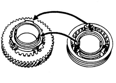
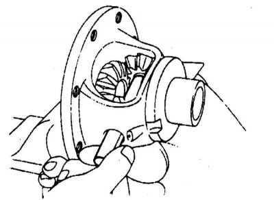
Removing the final drive assembly
Disassembly
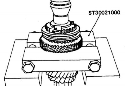
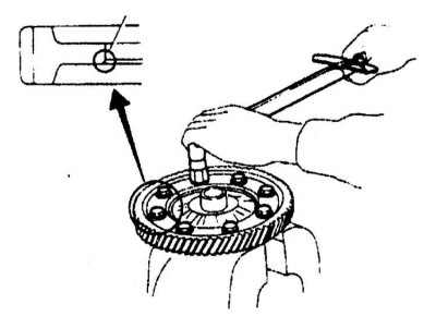
1. Turn out fixing bolts and remove a conducted ring gear wheel of the main transfer.
2. Remove the speedometer drive.
3. Press out the differential side bearings - remember that the right and left bearings are not interchangeable and must be planted strictly in their original places during installation.
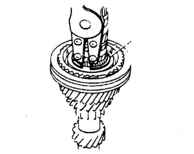
4. Release a fixing pin and take an axis of satellites.
5. Remove the satellites and side gears from the differential box.
Checking the Status of Components
1. Check the condition of the mating surfaces of the differential box, side gears and satellites.
2. Assess the degree of wear of the washers.
3. Check the freedom of rotation of the bearings. Check for signs of mechanical damage and pitting.
Assembly
1. Install washers on differential side gears. Fill the side gears and pinion gears in their regular places in the differential box.
2. Insert the satellite shaft.
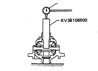
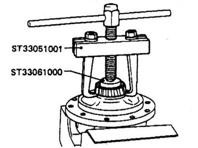
3. Using a special tool and a plunger-type dial gauge, measure the backlash of the side gear in the differential case.
4. The measurement result should not exceed 0.1÷0.2 mm, otherwise, achieve the required result by selecting new washers.
5. Install the pin.
6. Install the final drive gear.
7. Install the speedometer drive.
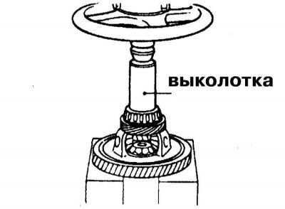
8. Press the side bearings onto the differential.
Checking the condition of gear selector components
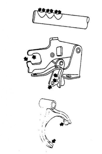
Check the sliding surfaces of the gear selector components for scratches, abrasions and other mechanical damage.