


Table of contents: Removal ↓ Installation ↓
Gear shift drive components
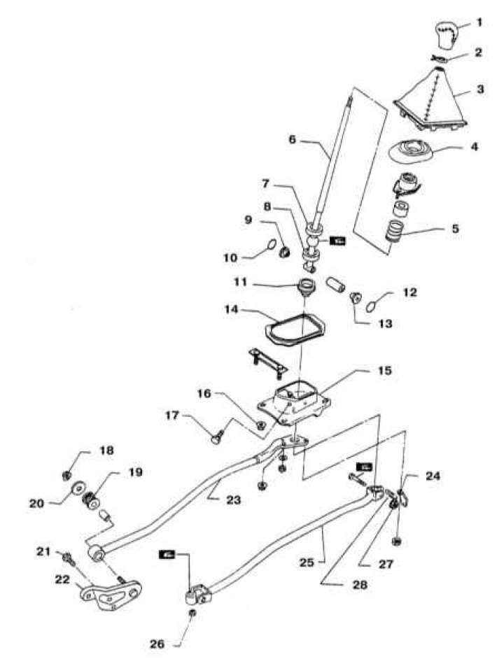
1 - Shift lever handle; 2 - Protective cover retainer; 3 - Lever protective cover; 4 - Dust cover; 5 - Spring; 6 - Gear shift lever; 7 - Upper bearing; 8 - Lower bearing; 9 - Bushing; 10 - Ring; 11 - Dust cover; 12 - Ring; 13 - Bushing; 14 - Rubber gasket; 15 - Holder; 16 - Nut (12÷15 Nm); 17 - Bolt (4.4÷5.9 Nm); 18 - Nut (35÷47 Nm); 19 - Bushing; 20 - Washer; 21 - Bolt (27÷36 Nm); 22 - Support rod holder; 23 - Support rod; 24 - Return spring suspension; 25 - Control rod; 26 - Nut (14÷18 Nm); 27 - Nut (16÷21 Nm); 28 - Return spring
Removal
Warning! Some models in this review are equipped with an additional restraint system (SRS). Before servicing components located near the airbags, be sure to deactivate the SRS system (see Chapter On-board electrical equipment).
1. Disconnect the negative battery cable. On models equipped with SRS, also disconnect the positive battery cable, then wait at least three minutes before proceeding with the procedure.
Warning! If the car stereo system is equipped with a security code, make sure you have the correct combination to activate the audio system before disconnecting the battery!
2. Jack up the vehicle and place it on supports. Remove the catalytic converter and heat shield.
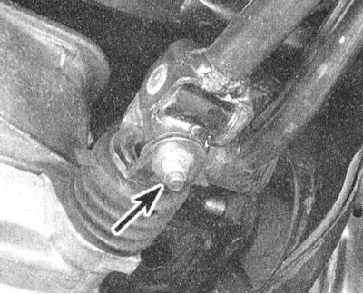
3. Disconnect the support rod and control rod from the transmission.
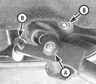
4. Loosen the nut securing the bolted connection of the shift control rod to the gear shift lever. Disconnect the return spring and loosen the nuts securing the support rod to the lever socket and the weight damper. Remove the gear shift drive assembly. Check the condition of the bushings at both ends of the support rod and the control rod. If cracks are found, replace the faulty components.
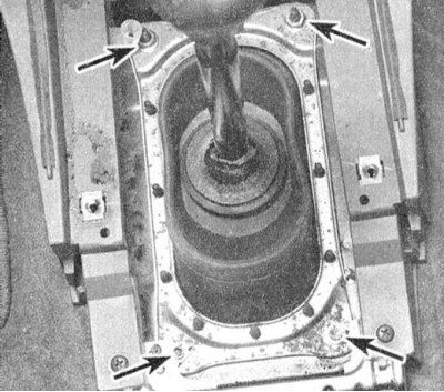
5. Remove the console (see Chapter Body). Disconnect the protective cover of the lever from the floor panel, release the gearshift lever and remove the cover, seat, insulator and receiving socket. Carefully check the condition of all components, in case of cracks, cuts, deformations and other mechanical damage, make the appropriate replacements. Of particular importance is the perfect condition of the receiving socket of the lever and its seat - excessive wear of these components leads to difficulties in shifting gears. It would also be reasonable to replace a torn or cut large protective cover of the lever.
Installation
Installation is carried out in the reverse order. Do not forget to lubricate all thrust and rubbing surfaces, including the spherical support of the lever and the inner surface of its receiving socket with silicone grease. Also lubricate the bushings of the control rod and support rod. Ensure that the fasteners are tightened securely.
[The publication is reprinted from this resource www.NissanBook.ru]