


Table of contents: Disassembly ↓ Assembly ↓
Disassembly
Attention: When disassembling the rear axle, it is necessary to mark the relative positions of the removed parts for correct installation during assembly.
- Place the rear axle on a suitable stand or support.
- Using a special key for the drive gear flange, unscrew the coupling flange nut.
- Using a puller, remove the connecting flange.
- Remove the coupling cover.
- Using a flat-blade screwdriver, remove the front oil seal from the clutch cover.
Caution: Be careful not to damage the coupling cover.
- Remove the electrically controlled clutch and washer from the pinion gear.
Note: Remember the correct position of the washer (beveled side) for proper installation during assembly.
- Using a puller, remove the front bearing from the electrically controlled clutch.
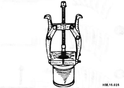
- If the bearing is being replaced with a new one, replace the washer located between the bearing and the coupling.
- Using a flat-blade screwdriver, remove the side seal from the pinion housing. Be careful not to damage the casing and back cover.
- Unscrew the bolts securing the back cover.
- Install the mandrel onto the adjusting washers of the right and left side bearings. To remove the pinion housing and rear cover, squeeze the differential case. The effort should be as little as possible. The maximum pressure should not exceed 10 kN.
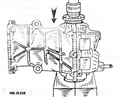
The differential case, side bearings and shims are compressed and fitted into the pinion housing and rear cover.
- Remove the adjusting washers and outer races of the side bearings. To subsequently install the parts in their previous positions, it is necessary to mark the adjusting washers of the right and left bearings.
- Loosen the ring gear mounting bolts and remove the ring gear from the differential case.
Elements of the rear axle final drive
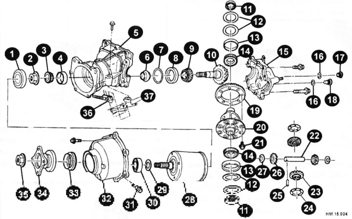
1 - central seal; 2 - drive gear nut; 3 — inner race of the front bearing of the drive gear; 4 — outer race of the front bearing of the drive gear; 5 — drive gear casing; 6 - deformable spacer sleeve; 7 — drive gear adjusting washer; 8 — outer race of the rear bearing of the drive gear; 9 — inner race of the rear bearing of the drive gear; 10 — drive gear; 11 - side seal; 12 — side bearing adjusting washer; 13 — outer race of the side bearing; 14 — inner race of the side bearing; 15 — back cover; 16 - gasket; 17 - filling plug; 18 — drain plug; 19 — ring gear; 20 — differential box; 21 — ring gear mounting bolt (8 pcs.); 22 — satellite shaft; 23 - side gear; 24 — side gear thrust washer; 25 - locking pin; 26 - satellite; 27 — satellite thrust washer; 28 - electrically controlled clutch; 29 — bearing adjusting washer; 30 — front clutch bearing; 31 - precision bolt (2 pcs.); 32 — electrically controlled clutch cover; 33 — front oil seal; 34 — connecting flange; 35 — connecting flange lock nut; 36 — electrically controlled clutch plug; 37 — bracket for electrically controlled clutch plug.
- Using a puller and a drift, remove the inner races of the side bearings (arrows).
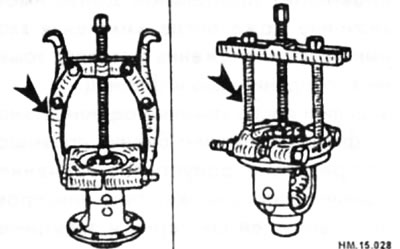
- Using a punch, knock the locking pin out of the satellite shaft.
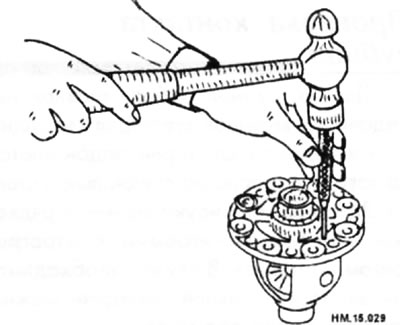
- Remove the pinion shaft, pinion gears, pinion thrust washers, side gears and side gear thrust washers from the differential case.
Caution: The differential should only be disassembled if any of its parts are broken or when replacing the axle gear washers and satellites.
- Install the pinion head onto the pinion splines. Using a special key, unscrew the drive gear nut.
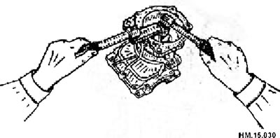
- Remove the center seal.
- Press the drive gear out of its housing.
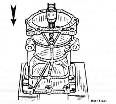
- Remove the inner race of the front pinion bearing.
- Remove the deformable spacer sleeve.
- Using a puller, remove the rear bearing inner race from the pinion gear.
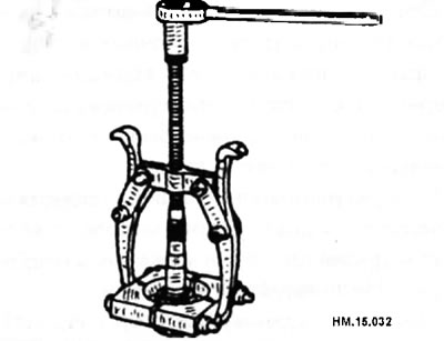
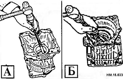
- Using a brass drift, evenly tap the outer race of the front pinion bearing (A) out of the two cutouts in the housing and remove the outer race. Be careful not to damage the pinion housing.
- In the same way, remove the adjusting washer and the outer race of the rear bearing of the drive gear (B).
Assembly
- Install the pinion adjusting washer with the same thickness as before disassembly. Using a drift (arrow), press a new outer race of the rear pinion bearing into the housing.
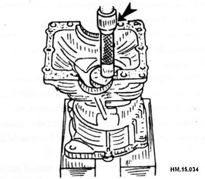
- First, use a hammer to tap the new outer bearing race into place until it is flush with the pinion housing.
- Using a drift, press the new pinion front bearing outer race into the pinion housing.
- Using a drift, press the new pinion rear bearing inner race onto the pinion gear.
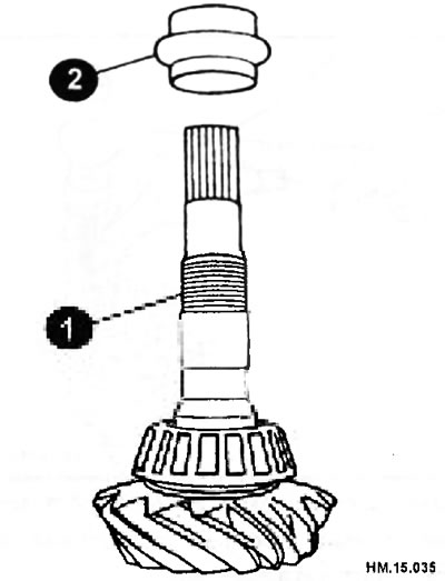
- After checking and adjusting the tooth contact pattern and hypoid gear backlash in accordance with the instructions below, install the new deformable spacer sleeve (2) onto the pinion gear (1). Be careful to observe the installation direction of the deformable spacer sleeve.
- Apply transmission oil to the pinion bearings and insert the pinion into the pinion housing.
Caution: Do not install the deformable spacer sleeve yet.
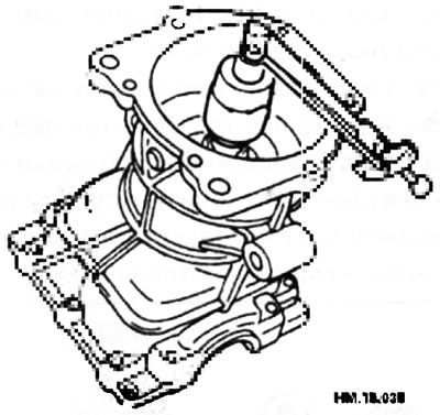
- Install the front pinion bearing inner race onto the pinion gear. Using a mandrel and press, press the pinion nut as far as it will go so that it can be tightened.
- Temporarily tighten the removed pinion nut onto the pinion gear. Use the removed pinion nut only for preload adjustment.
- Install the pinion socket onto the pinion splines. Using a special wrench, tighten the drive pinion nut to a torque of 181-361 N·m.
Caution: The pinion nut is tightened without the deformable spacer sleeve. Be careful not to overtighten the nut. When measuring preload, tighten it by 5-10°.
- Apply gear oil to the side bearings and install new side bearing shims of the same thickness as the old shims, or install the old shims in the same locations as before disassembly. Install the differential box into the pinion housing.
- To check and adjust the contact patch of the teeth, install the dummy cover and associated parts.
- Check and adjust the play as described above in the relevant section.
- Remove the dummy cover and associated parts and remove the differential case.
- Unscrew the drive gear nut, the inner race of the front drive gear bearing and remove the drive gear.
- Install the pinion gear with the deformable spacer sleeve into the pinion gear housing.
- Using a drift and press, press the pinion front bearing inner race onto the pinion gear as far as it will go so that the pinion gear nut can be tightened.
- Apply rust preventative oil to the threads and surface of the new pinion nut. Temporarily tighten the new pinion retaining nut.
- Install the pinion socket onto the pinion splines. Using a special key, adjust the tightening torque of the drive gear nut (181-361 N·m) and the preload of the drive gear bearings (0.69-1.17 N·m).
- First, adjust the lower torque value of the drive pinion nut.
- If the preload value exceeds the standard values, replace the deformable spacer sleeve and retighten the nut. Never loosen the pinion nut to adjust preload.
- After adjustment, rotate the drive gear in both directions 2-3 turns and check for any extraneous noise, difficulty in rotation, or other unusual phenomena.
- Install the central seal (arrow) so that there is a gap of 1 +0.2 mm between it and the edge of the casing.
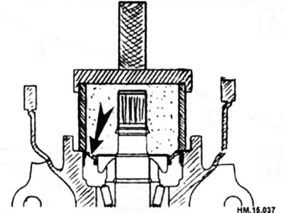
Note: If you do not want to disassemble the rear axle again after a relatively short period of time, then install new seals. Don't skimp!
- Install the differential box.
- Do not install the back cover.
- Install the dummy cover with associated parts and check the backlash, runout of the ring gear and contact of the teeth.
- Remove the dummy cover, then install the rear cover and insert the oil seal.
- Check the overall preload.
- Connect the electrically controlled clutch.
- Check the runout of the connecting flange.
- Install new side gear thrust washers. The washers must be the same thickness as the previous washers that were installed before disassembly. You can install old washers on the side gears.
- Install the side gears, side gear thrust washers, satellites and satellite thrust washers into the differential box. Temporarily install the satellite shaft.
- Measure the side gear end play according to the instructions below and select the side gear thrust washers. The side gear thrust washers have a thickness from 0.74 mm to 0.86 mm in 0.03 mm increments.
- While rotating the side gear, use feeler gauges to measure the clearance between the rear of the side gear and the differential case at three different locations. Determine the arithmetic mean of the three measurements and select the side gear thrust washer thickness so that the clearance matches the values specified in the "Check Dimensions and Adjustment Data" chapter. Measure the clearance on the other side gear. The standard value for side gear end play is no more than 0.2 mm. Each side gear should rotate smoothly and without binding.
- Before starting measurements, position the differential case so that the side gear whose play will be measured is at the top. To prevent the side gear from tilting, insert flat feeler gauges of the same thickness (arrows) on both sides.
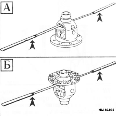
- Select thrust washers for the right (B) and left (A) side gears separately.
- Install the selected side gear thrust washers into the differential case.
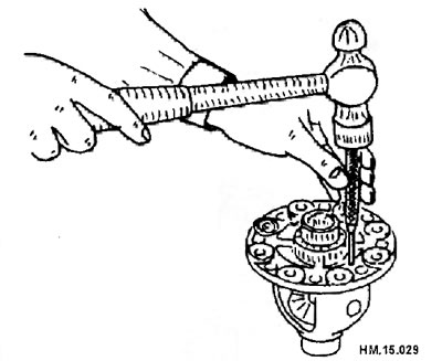
- Using a punch, drive a new locking pin into the hole in the satellite shaft.
- Using a mandrel, press the inner races of the side bearings into the differential case.
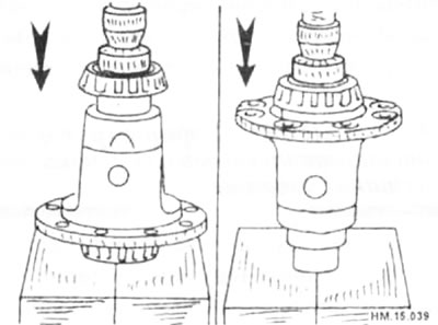
- Apply thread sealant to the threaded holes of the ring gear.
- The rear side, threaded holes of the ring gear and its mounting bolts must be cleaned and degreased.
- Install the ring gear onto the differential case and tighten the mounting bolts to 94-112 N·m.
- Apply transmission oil to the side bearings and install new side bearing adjusting washers (2 on each side) and the outer races of the side bearings in the differential box. New adjusting washers must be the same thickness as the washers installed before disassembly. You can use old washers. If the adjusting washers for the side bearings have already been selected, install them.
- Install the mandrel onto the adjusting washers of the right and left side bearings separately. To install the pinion housing onto the differential case, press the differential case and side bearings together.
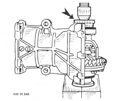
- The mandrel must be installed in the central part of the adjusting washers.
- When installing the drive gear housing onto the differential box, the pressing force should be as low as possible, no more than 1 ton.
- If the adjusting washers are installed by hammering, the pinion housing may be damaged. Do not use a hammer.
- Install the dummy cover with associated parts and adjust the backlash, ring gear runout, tooth contact and overall preload.
- Remove the dummy lid.
- Apply a continuous bead of thread sealant around the perimeter of the rear cover mating with the pinion housing, as shown in the figure (arrows). The overlap of the ends of the sealant bead should not exceed 3 mm.
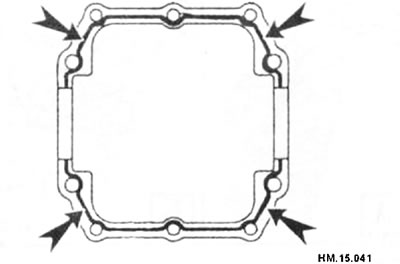
- It is necessary to remove old sealant, as well as traces of moisture, oil and foreign materials from the mating surfaces.
- Install the mandrel onto the adjusting washers of the right and left side bearings separately. To install the rear cover, squeeze the differential case and side bearings together.
- When installing the rear cover, the pressing force should not exceed 10 kN (1 ton).
- If the back cover is installed by hammering, it may be damaged. Do not use a hammer.
- Tighten the rear cover mounting bolts to 14-17 N·m (for M8 bolts) and 31-36 N·m (for M10 bolts).
- Using a drift, drive the new seal in until it is flush with the surface of the housing.
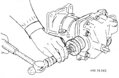
- The edges of the oil seal must be lubricated with a universal grease, and transmission oil must be applied to the circumference of the oil seal.
- Check the overall preload.
- Using a drift, install the front clutch bearing onto the electrically controlled clutch.
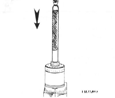
- When assembling, install a washer between the electrically controlled clutch and the bearing. When disassembling, it was necessary to remember the location of the beveled side of the washer.
- Install the electrically controlled clutch onto the drive gear.
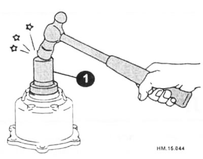
- Using a drift (1), drive in the new seal until it is flush with the surface of the casing.
- The edges of the oil seal must be lubricated with a universal grease, and transmission oil must be applied to the circumference of the oil seal.
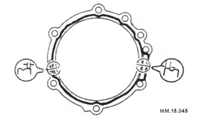
- Apply a continuous bead of thread sealant around the perimeter of the clutch cover that mates with the pinion housing as shown. The overlap of the ends of the sealant layer should not exceed 3 mm.
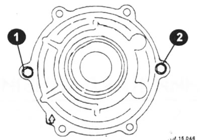
- Install the clutch cover onto the pinion housing with the arrow pointing up. Temporarily tighten precision bolts (1) and (2).
- Finally tighten the precision bolts and clutch cover mounting bolts to 14-17.5 N·m.
- Install the connecting flange.
- Using a special wrench, tighten the new connecting flange nut to a torque of 128.5-152 N·m.
- Check the runout of the connecting flange.
- Check the operation of the rear axle while the vehicle is moving. There should be no extraneous noise or knocking while driving. After driving continuously for 30-40 minutes, check the temperature of the rear axle in the area of the crankcase filler neck. The temperature should not exceed 95°C. If the neck temperature exceeds this value, the axle must be disassembled and the overall preload readjusted (add an adjusting washer).
Please note: In hot weather, after extended driving, the rear axle temperature may rise to 105°C.