


Table of contents: Checking the oil level in the rear…↓ Checking the overall bearing preload ↓ Checking and adjusting the play…↓ Checking the ring gear runout ↓ Checking the runout of the…↓ Checking the contact of the teeth ↓
Checking the oil level in the rear axle
The rear axle should be greased with API GL5, MIL-L-2105 B or C, or equivalent, with a viscosity of SAE 90. If the air temperature drops below 10°C, use SAE 80.
Use oils with the required additives for vehicles equipped with a limited slip differential.
The lubricant level should be checked every 15 thousand km.
- Raise and securely support the vehicle.
- Remove the rear axle inspection plug.
- Check that the oil level reaches the bottom of the inspection hole. Add oil if necessary.
- Tighten the check plug and lower the vehicle.
Checking the overall bearing preload
Adjustment of the differential bearing preload is performed after prolonged use of the vehicle, during repair of the rear axle. The tension is adjusted by changing the number of shims installed between the inner bearing rings and the differential box.
- Drain the oil.
- Remove the electrically controlled clutch.
- Rotate the pinion gear back and forth 2-3 turns and check for any unusual noise or difficulty in rotation.
- To check the operation of the bearings, rotate the drive gear at least 20 revolutions.
- Install the pinion socket onto the pinion splines. Measure the preload using a torque wrench (arrow).
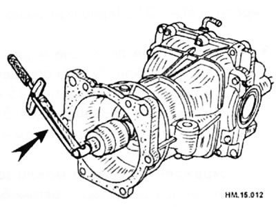
- If the measured preload is not within the range of 1.33-2.15 N·m, check and adjust each part. Adjust the pinion bearing preload first, then the side bearing preload. The side bearing preload should be 0.64-0.98 Nm.
- If the preload is too great:
For pinion bearings: replace the deformable spacer sleeve.
For side bearings: Use side bearing adjusting washers with a thinner thickness.
- If the preload is too low:
For pinion bearings: Tighten the pinion nut.
For side bearings: Use thicker side bearing adjusting washers.
Checking and adjusting the play between the ring and pinion gears
- Drain the oil from the differential.
- Remove the back cover.
- Install the dummy cover washers onto the right and left side bearing adjusting washers.
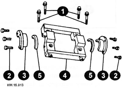
1 - rear cover mounting bolts; 2 - bolts for fastening the remote part of the dummy cover; 3 - remote part of the imitation cover; 4 - imitation lid; 5 - washers of the dummy cover.
- Temporarily secure the dummy cover to the pinion housing.
- Install the dummy cover spacer onto the dummy cover.
- Tighten the rear cover spacer mounting bolts to 31-36 Nm.
- Tighten the cover spacer mounting bolts to a torque of 5.9 N·m.
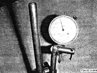
- To determine the backlash, install a dial indicator on the front side of the ring gear.
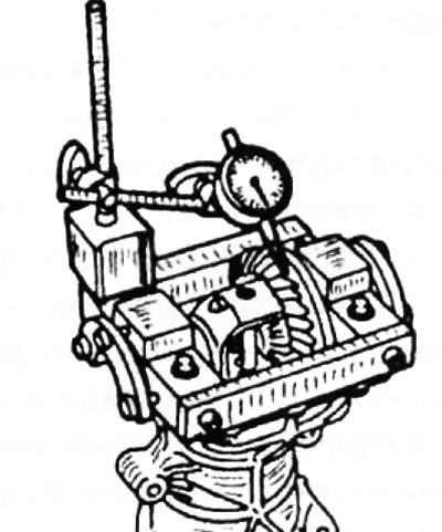
- If the measured clearance is not within the range of 0.10-0.15 mm, change the thickness of the adjusting washers for the side bearings.
- If the play is too large: install thicker rear and thinner front ring gear adjusting washers.
- If the play is too small: install thinner rear and thicker front ring gear adjusting washers.
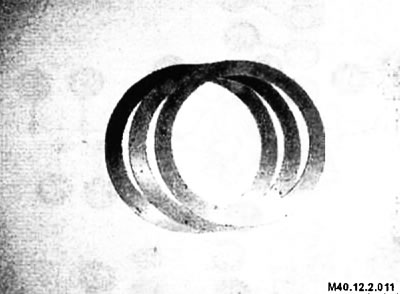
To adjust the ring gear play, side bearing adjusting washers with sizes ranging from 1.85 mm to 2.35 mm in 0.05 mm increments are used. The adjusting washers' numbers according to their thickness are listed in the chapter "Control dimensions and adjustment data".
Checking the ring gear runout
- Drain the oil from the differential.
- Remove the back cover.
- Install the dummy cover with the accompanying parts onto the drive gear housing as described above.
- To determine the backlash, install a dial indicator on the back side of the ring gear.
Data taken from this portal Nissanbook.ru
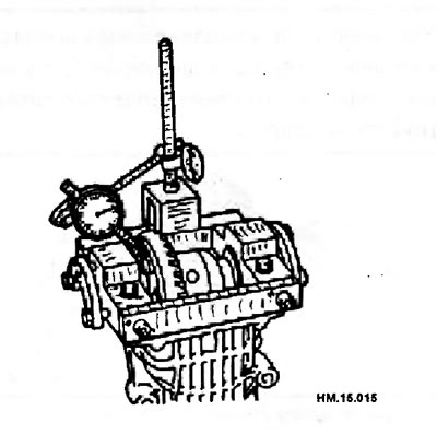
- To determine the runout value, rotate the ring gear. If the runout exceeds 0.05 mm, check the condition of the ring gear. Foreign particles may get between the ring gear and the differential case, which may cause deformation of the differential case, ring gear, etc.
Caution: The ring gear and pinion gear must be replaced as a set.
Checking the runout of the connecting flange
- Install the dial indicator on the surface of the connecting flange (on the inside of the holes for the cardan shaft mounting bolts). To check the runout, rotate the connecting flange.
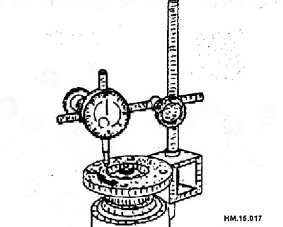
- Install the dial indicator on the inside of the connecting flange (by outer diameter). To check the runout, rotate the connecting flange.
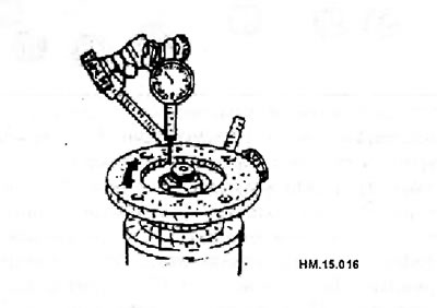
- If the runout value exceeds 0.13 mm, make adjustments:
♦ Check the runout by changing the relative position of the coupling flange and the drive gear by turning it 90°. Find the position in which the runout is minimal.
♦ If the runout value still exceeds the maximum permissible value even after changing the relative position of the parts, replace the connecting flange.
♦ If, even after replacing the connecting flange, the runout value exceeds the maximum permissible value, this may be due to a faulty drive gear and electrically controlled clutch, a faulty clutch bearing, or a faulty electrically controlled clutch itself.
Checking the contact of the teeth
For silent operation of the main gear, its drive gear (drive shaft) and driven gears are selected in pairs at the factory on a special stand. Then they are marked with one serial number, burned with electrographite on the ends. If necessary, the main transmission gears can only be replaced both at once.
The main indicator of the correct engagement of the main transmission gears when they are selected at the factory is the location of the contact patch on the surface of the teeth, which is obtained during the running-in of the gears on the stand. To obtain a clearly visible contact patch, the teeth of one of the gears are first coated with a thin layer of paint.
The figure shows the location of the contact patch on the working surfaces of the gear teeth.
Adjusting the gears by the contact patch
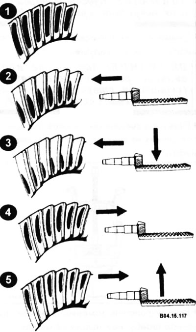
1 - correct contact of teeth; 2 - strong contact of teeth, shifted towards the center. Move the drive gear further away from the driven gear; 3 - strong contact of the ends of the teeth. Move the drive gear away from the driven gear and the driven gear away from the drive gear; 4 - strong contact of the rear parts of the teeth and displacement towards the center. Move the drive gear toward the driven gear. 5 - strong contact of the rear parts of the teeth with the front side. Move the drive gear to the driven gear, and the driven gear to the drive gear.
It is unacceptable for the stain to extend to the outer half of the tooth, for the stain to be located at the root of the tooth, or for the stain to split. It is absolutely unacceptable for the contact spot to extend to the upper edge of the tooth and to the edge at the outer end of the tooth.
To adjust the pinion height, use adjusting washers ranging in size from 1.70 mm to 2.24 mm in 0.03 mm increments. The adjusting washers' thickness numbers are listed in the "Control Dimensions and Adjustment Data" chapter at the end of this book.