


Table of contents: Checking the backlash ↓ Checking the contact of the teeth ↓ Preload ↓ Total preload ↓
Checking the backlash
- Install the bolt onto the connecting flange.
- Install a dial indicator on the bolt.
- Measure the clearance around the circumference of the connecting flange and make sure that the clearance value is 0.13-0.19 mm.
- If the measured clearance does not correspond to the specified values, disassemble the transfer case and make adjustments.
Checking the contact of the teeth
- Remove the drive gear bushing.
- Apply red paint to both sides of 3-4 pinion teeth located at 4 equal distances around the circumference of the pinion.
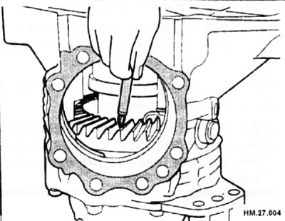
- Install the pinion bushing adjusting washers and pinion bushing.
- Remove the plug from the top of the transfer case housing. When reinstalling the plug, apply the recommended type of sealant to its threads and tighten the plug to a torque of 15-19 N·m.
- Rotate the coupling flange back and forth several times and check the contact of the pinion and ring gear teeth by observing them through the plug hole.
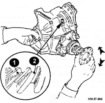
1 - leading side; 2 - reverse side.
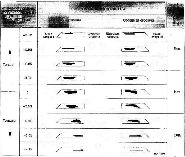
- Check the condition of the contact area of the scars according to the table.
- If the tooth contact is not adjusted correctly, adjust the pinion height as described below.
- In case of top contact on the wide side of the teeth or point contact, to move the pinion gear closer to the ring gear, the thickness of the adjusting washers for the pinion gear must be reduced.
- In the case of bottom contact on the narrow side of the teeth or "heel" contact, to move the pinion gear further from the ring gear, the thickness of the adjusting shims for the pinion gear must be increased.
Preload
Preload of pinion bearings
- Remove the drive gear bushing.
- Rotate the connecting flange back and forth 2-3 times.
- Check for unusual noises, difficulty rotating, or other abnormal phenomena.
- To check the smooth operation of the bearings, rotate the connecting flange at least 20 times.
- Using a torque wrench (arrow), measure the torque required to turn the pinion bearing. It should be 0.10-0.39 N·m.
Caution: Each rotating part must rotate evenly in the transmission oil.
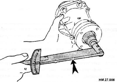
- If the measured preload is different from the standard values, disassemble the pinion gear to check and adjust each part.
Total preload
- Measure the preload of the pinion gear (P1) bearings. It should be 0.10-0.39 N·m.
- Install the pinion bushing adjusting washers and pinion bushing.
- To check the smooth operation of the bearings, rotate the connecting flange at least 20 times.
- Using a preload measuring device, measure the total preload, which should be as follows:
♦ All seals are installed: P1 + (0.1 9±0.03) N·m.
♦ Without transfer case oil seal and ring gear oil seal: P1 + (0.09±0.03) N·m.
- If the measured preload differs from the specified values, remove each part to check and adjust them. If the total preload is measured after disassembly, measure it with the transfer case seals and ring gear seals removed, and then install the seals.
Runout of the connecting flange
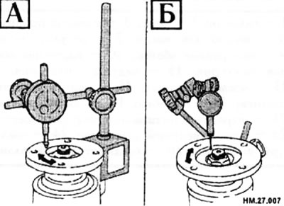
- Install the dial indicator on the surface of the connecting flange (on the inside of the holes for the cardan shaft mounting bolts) (A).
- To check the runout, rotate the connecting flange. Maximum permissible runout: 0.1 mm.
- Install the dial indicator on the inside of the connecting flange (by outer diameter) (B).
- To check the runout, rotate the connecting flange. Maximum permissible runout: 0.1 mm.
- If the runout value exceeds the maximum permissible value, check the runout by changing the relative positions of the coupling flange and the drive gear by 90°. Find the position at which the runout is minimal.
- If the runout value exceeds the maximum permissible value and after changing the relative position of the parts, replace the connecting flange.
- If the runout value still exceeds the maximum permissible value after replacing the coupling flange, check the installation of the pinion bearings or replace the pinion bearings.