Removing
Since the removal of one part affects the removal of another part, the work is described together. In the illustrations View of the assembled rear suspension from one side (with disc brakes) and Elements of the disassembled rear suspension parts are shown in the assembled state in the form of a wiring diagram. Based on these illustrations:
1. Remove the rear seat, remove the top shock mount and unscrew the three nuts from the top side of the shock absorber. Do not unscrew the nut in the middle (piston rod nut), however, it can be unscrewed under certain circumstances. In this case, the car must be on wheels.
2. Put the rear of the car on wheels and unscrew the rear wheels. Engage first gear or reverse to prevent the vehicle from rolling off the supports. Leave a lift under the rear cross member.
3. Remove the union nut of the brake pipe at the connection with the brake hose, remove the pipe from the hose and knock the spring plate out of the hose. Remove the hose from the mounting plate.
4. Unscrew the stabilizer bar from the suspension strut and disconnect it.
5. Unscrew from the underside of a depreciation rack both nuts and bolts of an amortization rack from the holder of a nave of a wheel and carefully knock out bolts. Insert a screwdriver into the spring strut clamping slot and slowly press the hub holder down until it is free from the spring strut.
6. Take out an amortization rack down. Check which side the gasket is on, as it may remain on the body.
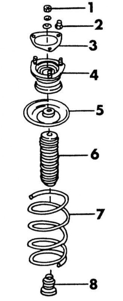
Elements mounted on the rear suspension strut
1 - nut, 60-80 Nm; 2 - nut, 43-55 Nm; 3 - gasket; 4 - shock absorber support; 5 - upper spring cup; 6 - dustproof cuff; 7 - helical spring; 8 - compression stroke buffer
Dismantling the suspension strut
Details of the disassembled suspension strut are shown in illustrations. The suspension strut itself can be seen on illustrations.
1. Clamp the underside of the shock absorber in a vise. To avoid squeezing the clamping element, you can insert the socket before tightening the vise.
2. Install the compressor on the coils of the spring, as shown for the front springs, and completely unscrew the nut in the middle of the shock absorber. Remove from the rack all those shown on illustrations elements. Both rack posts are installed in a specific position that should be marked before removing the posts. On a car with a carburetor engine, two suspension struts with different piston rod diameters are installed. The compression stroke buffers must be replaced along with the suspension strut.
3. If you only need to replace the spring, no other work is required.
4. Check the shock absorber by clamping it vertically in a vise, squeezing and stretching it. The pressure must be the same throughout the piston stroke. When jerking, the shock absorber should be replaced.
5. Order rear springs from the catalog.
Shock absorber assembly
1. Clamp the shock absorber in a vise.
2. Put the compressed spring on the post. Check that the spring fits into the contour of the cup, as shown in the illustration. The spring has a flat end at one end. This side should be facing up. In addition, the spring is marked with one and two marks. The two marks should be on the underside.
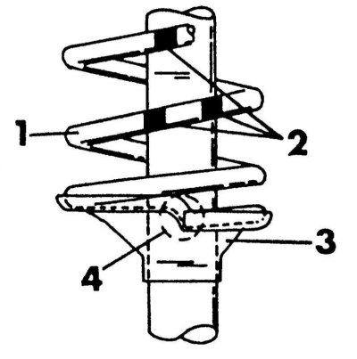
Elements for installing the rear spring
1 - helical spring; 2 - color designations; 3 - lower spring cup; 4 - install the horses, springs in the place indicated by the circle
3. Slide the shock absorber support onto the piston rod and turn to match the marks made during removal. If this is overlooked, you need to focus on the illustration above. Each suspension strut mount has a pilot hole and the spring seat must be rotated until the spring seat is aligned on the left or right side as shown.
4. Screw on a new nut and tighten with a force of 60-80 Nm. The flattening at the end of the piston rod serves to keep the piston rod from turning.
Installing the suspension strut
1. Connect the hub holder to the suspension strut, align the threaded holes and drive in the bolts from the side of the anti-roll bar. Screw on the nuts and tighten with a force of 100-120 Nm.
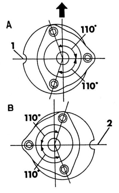
Proper installation of suspension strut mounts. Arrow facing forward
A - left side
B - right side
2. Fix the shock absorber on the top side with three nuts (put on a gasket) and tighten the nuts with a force of 45-55 Nm.
3. Attach the bar of the stabilizer bar and tighten the nut with a force of 42-48 Nm.
4. Perform all other work in reverse order.
5. Remove air from the brake system.