Attention! The procedure described below applies only to gearboxes before 1993. Repairs to gearboxes after 1993 are carried out in a car service.
1st stage of disassembly
1. Clean and wash the gearbox housing.
2. Remove the lever cover from the clutch housing.
3. Remove the release bearing and hub together with the lever (Ch. 8).
4. Remove all switches from the gearbox housing (photo).
4.4 Remove the switches from the gearbox housing
5. On rear-wheel drive vehicles, unscrew the bolts and remove the speedometer gearbox (photo).
4.5 Removing the speedometer gearbox
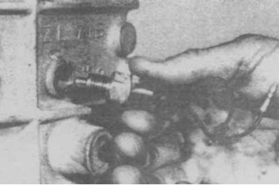
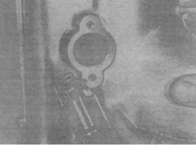
6. Remove the retaining ring and knock out the pin (photo).
4.6 Removing the pin
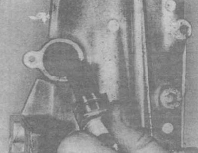
7. Turn out a plug, get a spring and a plunger (photo).
4.7 Removing the plug.
8. Turn away two screws and get the restrictive plug of a backing (photo).
4.8 Reverse stop sleeve
9. Remove the two bolts and separate the rear cover from the gearbox housing (photo).
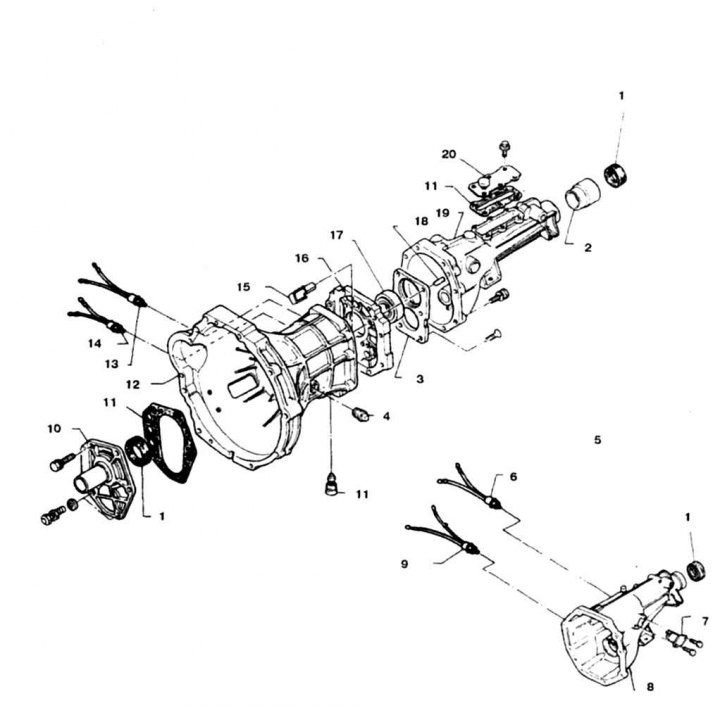
4.9a Details of the crankcase of 4 and 5-speed gearboxes of early production
1.Gland; 2. Dust cover; 3. Bearing housing; 4. Filler plug; 5. 5-speed gearbox; 6. Neutral position switch; 7. Reverse limit bushing; 8. Back cover
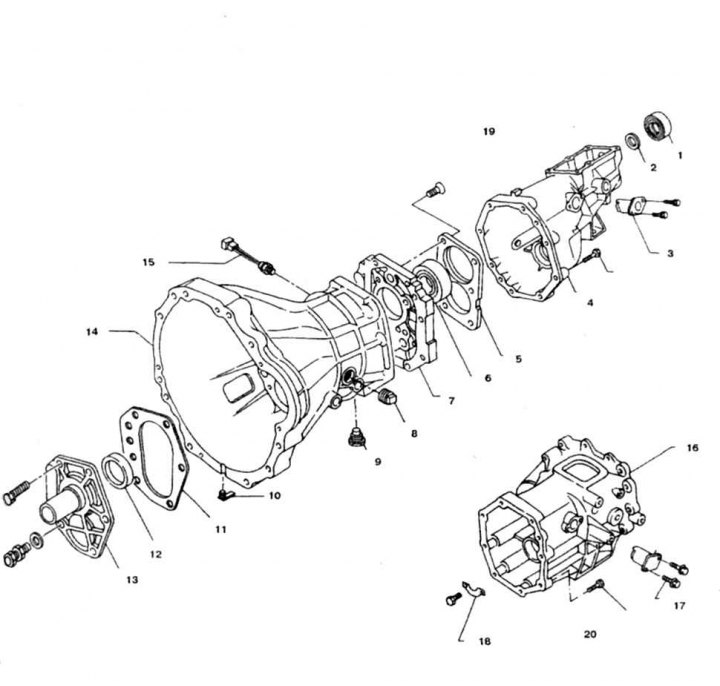
4.9b Crankcase details 5-speed gearbox FS5W71B/C
1. Dust cover; 2, 12. Oil seal; 3, 17. Reverse limit bushing; 4. Back cover; 5. Bearing housing; 6. Bearing; 7. Transition section; 8. Filler plug; 9. Drain plug
10. Turn away bolts and remove a forward cover, get an adjusting washer and a lock ring of the bearing (photo).
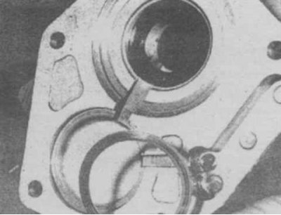
4.10 When removing the front cover, the shim falls out
11. Separate and remove the gearbox housing.
12. Clamp the transition section of the crankcase in a vise by bolting the auxiliary plate (make your own).
13. Knock out shift fork pins (photo).
14. Turn out all three caps of clamps.
15. Remove the fork stems (photo).
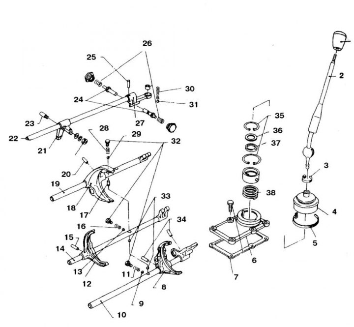
4.15a Details of the gearshift mechanism for a gearbox manufactured before 1993
1. Lever; 2. Lever; 3. Upper retaining ring of the cover; 4. Case; 5. Lower collar; 6. Lid; 7. Gasket; 8. Fork of inclusion of 5th transfer and a backing; 9, 13, 29, 31, 33. Retainer ball
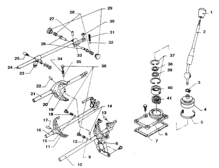
4.15b Details of the gearshift mechanism for a gearbox manufactured after 1993 (for rear wheel drive vehicles)
1. Lever; 2. Lever; 3. Upper retaining ring of the cover; 4. Case; 5. Lower collar; 6. Lid; 7. Gasket; 8. 5th gear and reverse fork
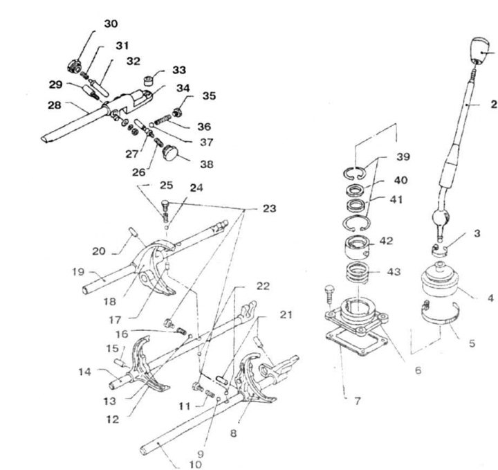
4.15v Details of the gearshift mechanism of the gearbox manufactured after 1993 (for all-wheel drive vehicles)
1. Handle; 2. Lever; 3. Upper retaining ring of the cover; 4. Case; 5. Lower collar; 6. Lid; 7. Gasket; 8. 5th gear and reverse fork
16. In process of extraction of rods get plugs and balls with springs. The smaller diameter balls are the retainer balls.
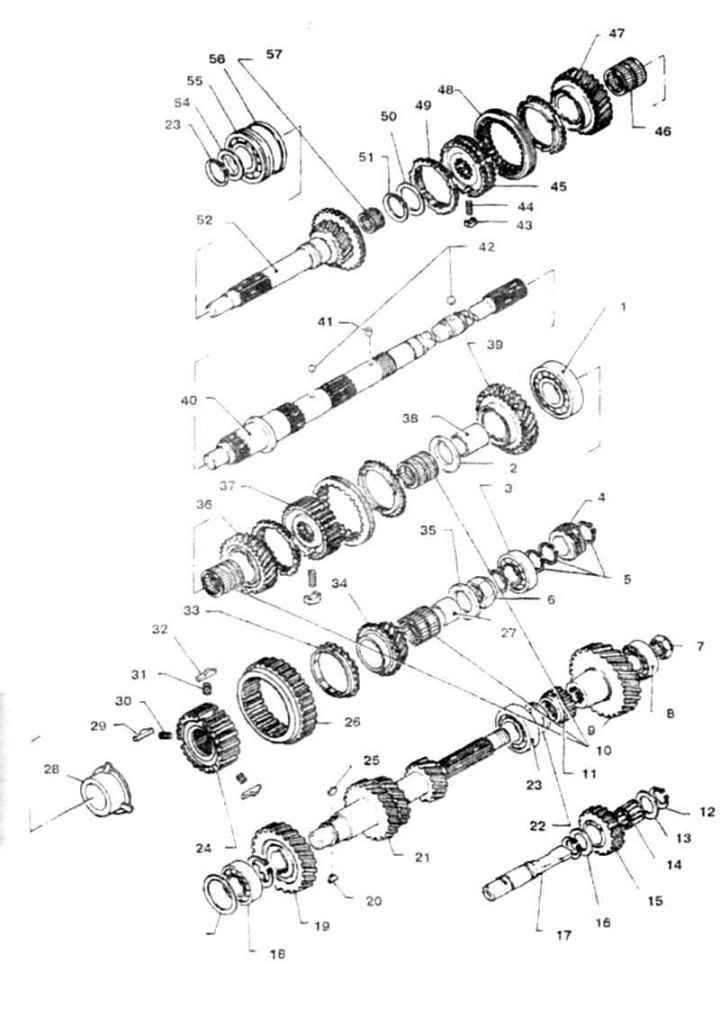
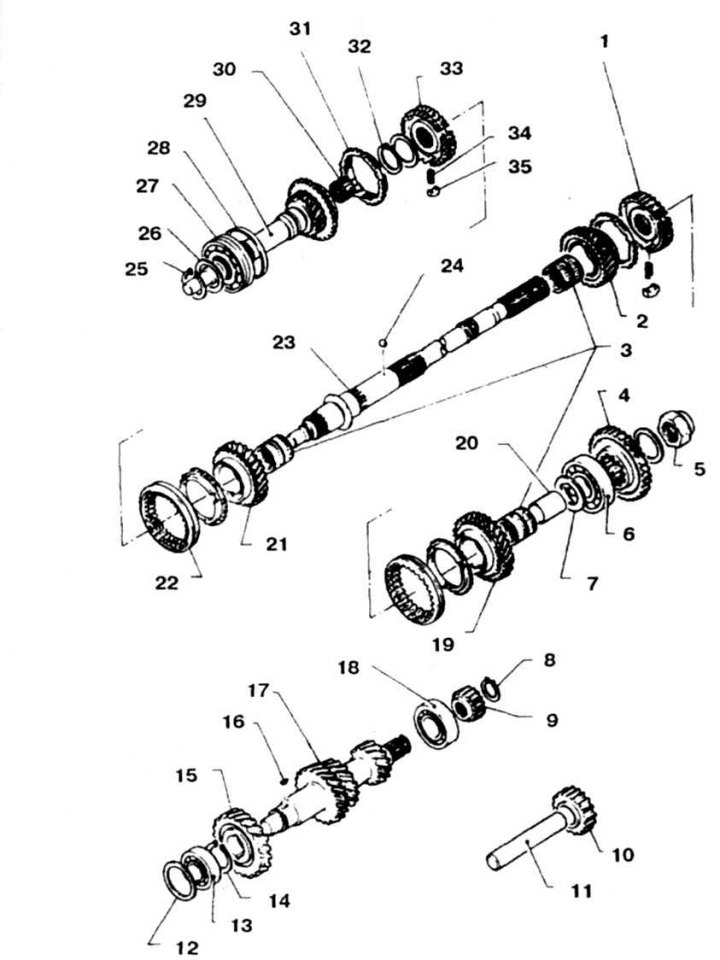
4.17a Gearbox parts FS5W71B/C (until 1993)
1. Output shaft bearing; 2, 13, 16. Thrust washer; 3. Bearing of the driven gear of the 5th gear; 4. Drive gear speedometer reducer; 5, 12, 51, 53, 56. Retaining ring; 6, 7. Nut; 8. Rear intermediate shaft bearing
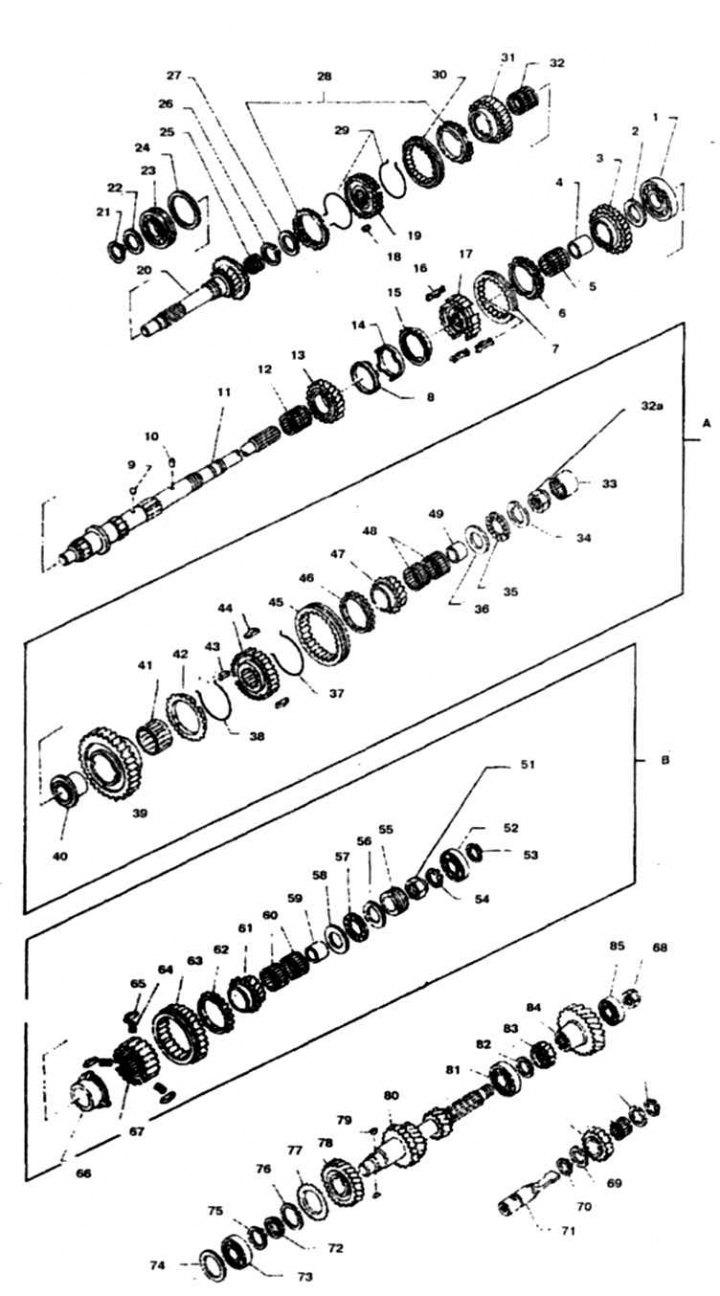
4.176 Gearbox parts FS5W71B/C (after 1993)
1. Output shaft bearing; 2, 13, 16. Thrust washer; 3. Driven gear 1st gear; 4. Sleeve; 5, 12, 32. Needle bearing; 6, 28. Synchronizer blocking ring; 7, 30. Synchronizer clutch; 8. Internal
4.17c Details of the 4-speed gearbox F4W71B/C
1. Synchronizer hub for 1st and 2nd gears; 2. Driven gear 2nd gear; 3. Needle bearing; 4. Reverse driven gear; 5. Nut of the secondary shaft; 6, 13, 27. Bearing; 7. Thrust washer; 8, 25, 28, 32, 34. Retaining ring
4.18 Checking the axial play of the gearbox gears
1. Gear; 2. End gap; 3. Output shaft or sleeve
19. If damage is observed and the play exceeds the norm, then completely disassemble the gearbox and replace worn parts
20. Press the front intermediate shaft bearing with a puller.
21. Get a lock ring.
22. Carefully remove the intermediate and primary shafts.
23. Remove the circlip and thrust washer from the input shaft.
24. Remove the 3rd and 4th gear synchronizer and 3rd gear.
25. Straighten with a hammer and a beard the pierced sections of the nuts of the secondary and intermediate shafts.
26. Remove reverse gear and shim.
27. Press the 5th gear and bearing
28. Remove the intermediate shaft nut (nut to be replaced).
29. Remove the circlip and remove the reverse idle gear.
30. Get a lock ring and remove a gear wheel of a reducer of a speedometer.
31. Get 2 lock rings and remove the bearing of a secondary shaft.
32. Remove the input shaft nut (nut to be replaced).
33. Remove the thrust washer, bushing, needle bearing, 5th gear, reverse driven gear, synchronizer and cage.
34. Carefully knock out the secondary and intermediate shafts from the transition section.
Output shaft
35. Check the condition of the shaft splines and gear teeth, disassemble and replace worn gears.
36. Check the condition of the shaft (wear of splines, violation of their straightness, wear, taper).
37. Check the condition of the synchronizers, especially if the operation of the checkpoint was accompanied by noise.
38. Install tightly blocking rings on the gears and check the clearance between the ring gear (photo).
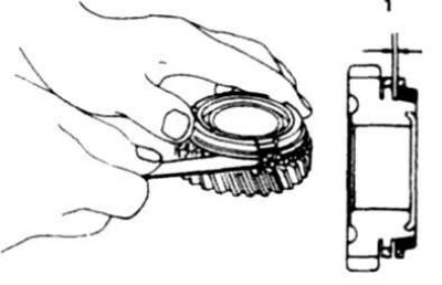
4.38 Checking the gap between the crown of the drive gear and the synchronizer blocking ring
1. Clearance
39. When assembling the synchronizer, make sure that the ends of the retaining rings on both sides of the hub go into different grooves.
40. Start the assembly by installing the needle bearing on the secondary shaft. Then install the 2nd gear, blocking ring and 1st and 2nd gear synchronizer, being careful to install correctly.
41. Install 1st gear lock ring, needle bearing, ball (grease before assembly), washer, bushing and 1st gear.
Intermediate shaft
42. The front bearing of the intermediate shaft is removed when disassembling the gearbox.
43. The rear shaft bearing remains in the transition section of the crankcase.
44. Remove the drive gear and remove the 2 keys.
45. Check the condition of the shaft splines and gear teeth.
46. Assembly is carried out in the reverse order.
Input shaft
47. Remove the circlip and shim.
48. Press the bearing (to be replaced).
49. Press the new bearing into the outer race.
50. Put on the puck.
51. Choose a washer in thickness so as to compensate for axial play.
Oil seals
52. Press out the rear oil seal and press in a new one.
53. Install the speedometer gear gear O-ring.
54. Replace the front oil seal by pressing in a new one using a mandrel.
Rear crankcase
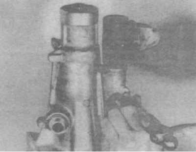
55. Loosen the slider rod pin nut, unscrew halfway.
56. Press out the pin, holding the nut (photo).
4.56 Removing the pin from the slider rod
57. Remove the lever from the stem and remove the stem.
58. Check up a condition of a rod and the lever, if necessary replace. Replace stem seal.
59. Check up a condition of the plug in back part of section at detection of cracks or deterioration replace a section.
60. Install the slider rod in reverse order.
Assembly
61. Remove the bearings of the intermediate and secondary shafts from the transition section of the crankcase and check their condition. To do this, unscrew the 6 screws of the holder on the transition section.
62. Press out the bearings against the outer races.
63. After washing, check the freedom of rotation of the bearings. Replace bearings if seized, noisy, or loose in races.
64. Check that the drive pins are pressed into the transition section of the crankcase.
65. Press the bearings into the transition section with light taps.
66. Press the shaft of the intermediate gear into the transition section for 2/3 of its length so that and into the slot
the bearing retainer plate entered the roller.
67. Install the lock plate and tighten the screws to the specified torque.
68. Loosen the screws to prevent loosening.
69. Carefully press the intermediate shaft rear bearing into the transition section.
70. Press the secondary shaft into the transition section, abutting the inner race of the bearing.
71. Press in the intermediate shaft.
72. Put the needle bearing, 3rd gear, blocking ring and 3rd and 4th gear synchronizer on the secondary shaft.
73. Install thrust washer and retaining ring in thickness to minimize end play (see table below).
74. Put on a primary shaft the directing needle bearing.
75. Enter the input shaft drive gear into engagement with the 4th gear. Enter the input shaft with the drive gear into engagement with the secondary and intermediate shafts. Press the output shaft gear with a piece of pipe of suitable diameter.
76. Install the countershaft pinion circlip, sizing it to the correct thickness to minimize end play (see table below).
77. Using a mandrel, press the bearing onto the intermediate shaft.
78. Put the reverse gear spacer on the intermediate shaft.
79. Install the circlip, thrust washer, needle bearing, reverse idle gear, idler thrust washer, and rear circlip onto the idler shaft.
80. From the rear side of the secondary shaft, install the clip (if provided), synchronizer, reverse driven gear, bushing, needle bearing and blocking ring.
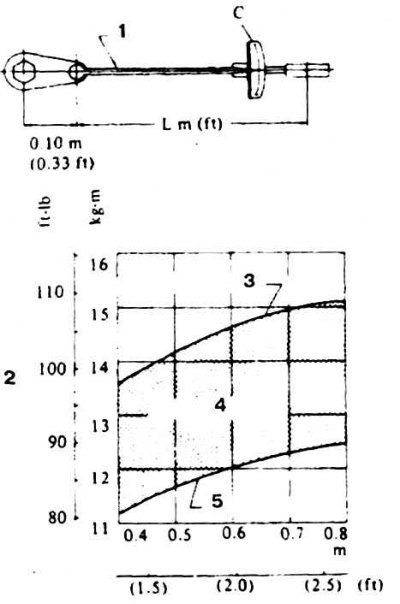
4.85 Dependence of the actual tightening torque (with extension) from the indication on the key scale
1. Torque wrench; 2. Readable moment; 3. Upper limit; 4. Converted moment; 5. Lower limit
81. Put the reverse drive gear on the intermediate shaft.
82. Engage both 5th gears and put them on the intermediate and secondary shafts.
83. Lubricate the ball with grease and install the ball and thrust washer from the back of the output shaft.
84. Wrap a new nut of a secondary shaft and tighten with the set moment.
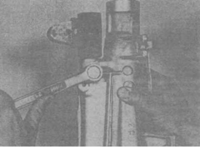
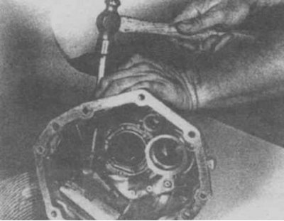
Attention! To tighten the nut of the output shaft of the gearbox with a given torque, an extension cord should be used on the torque wrench (photo). In this case, determine the actual tightening torque from the attached diagram (photo).
4.84 Tightening the output shaft nut
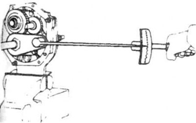
85. Put on the rear bearing of the intermediate shaft (photo).
86. Tighten the layshaft nut to the specified torque.
87. Open the nuts of the shafts so that the rims of the nuts go into the recesses on the shafts.
88. Check gear end clearance (see above).
89. Put on a secondary shaft a lock ring and press on the back bearing.
90. Select the thickness of the rear retaining ring (see table).
91. Install the retaining ring, lubricate the ball and install the ball and the speedometer gearbox drive gear on the output shaft. Install the outer retaining ring.
92. Install the fork on the synchronizer clutch fork 1st and 2nd gear. The extended part of the yoke must face the intermediate shaft. Install the fork on the 3rd and 4th gear synchronizer clutch. The extended part of the plug must be facing the opposite direction.
93. Install the fork on the 5th and reverse gear synchronizer clutch. The top hole of the fork stem must be in line with the 3rd and 4th gear forks.
94. Insert the 1st and 2nd gear fork rod into the hole in the adapter section and into the fork. Line up the holes and press in a new pin.
95. Align the recess in the stem with the hole and insert the ball, spring and wrap the plug, lubricating lightly with sealant.
96. Turn over the transition section with shafts and forks so that the assembled retainer is in its lowest position. Insert 2 balls into the hole for the 3rd and 4th gear detent and use a thin tool to push the balls all the way into the 1st and 2nd gear fork shaft (if the transition section is installed correctly, then the balls should go into place). Pass the 3rd and 4th shaft through the top hole in the 5th and reverse forks and the adapter section and insert into the 3rd and 4th forks. The balls must be between the stem to be installed and the stem of the 1st and 2nd gear forks. Align the yoke and stem holes and press in a new pin. Insert a ball, a spring into the hole of the retainer of the 3rd and 4th gears and wrap the plug, lubricating lightly with sealant. Before installing the detent ball, make sure that the groove of the stem aligns with the hole.
97. Insert 2 balls into the remaining hole in the retainer. Insert the 5th gear and reverse fork rod into the hole in the fork and adapter section. Make sure the balls are between the stem to be installed and the stem of the 3rd and 4th fork. Make sure that the hole of the retainer matches the notch on the stem and insert the ball, spring into the hole and wrap the plug on the sealant. Align the holes of the yoke and the stem to be installed and press in the new pin.
98. Torque all 3 plugs.
99. Lubricate the rods and check the smoothness of their movement.
100. Clean the split planes of the crankcase and transition section and lubricate with sealant.
101. Carefully put the crankcase on the transition section, making sure that the bearings of the intermediate and secondary shafts go into the grooves of the crankcase. Siege the crankcase in place with light blows.
102. Install the input shaft bearing circlip.
103. Clean the split planes of the transition and rear sections, lubricate with sealant.
104. Move the forks to the neutral position and install the rear section, the slider lever should engage the gear selection rods.
105. Tighten the crankcase section bolts to the specified torque.
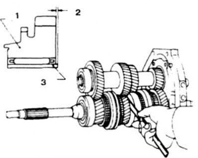
106. Check protrusion A of the front bearing of the intermediate shaft relative to the plane of the crankcase (photo) and select the adjusting washer according to the thickness (see table).
Table
| Measurement (mm) | Washer thickness (mm) |
| 2,92-3,01 | 0,6 |
| 3,02-3,11 | 0,5 |
| 3,12-3,21 | 0,4 |
| 3,22-3,31 | 0,3 |
| 3,32-3,41 | 0,2 |
| 3,42-3.51 | 0,1 |
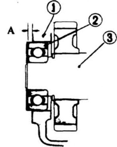
4.106 Checking protrusion A for adjusting the thickness of the shim
1. Carter; 2. Bearing; 3. Intermediate shaft
107. Fix the washer with grease and put on the front cover with a new oil seal and a new gasket without damaging the oil seal.
108. Lubricate with sealant and tighten the cover bolts to the specified torque.
109. The remaining operations are performed in reverse order.