General information
Several types of towbar connectors are available with different terminal arrangements in them. The most common is the 7-pin connector, which provides two additional circuits commonly used to supply power to trailer reversing lights and electric brakes.
When equipping a towbar, it may be necessary to replace the previous turn signal breaker with a more powerful one in order to maintain the flashing frequency of signal lights specified in the traffic rules adopted in a particular region. The authorities of some regions also prescribe the mandatory installation of turn signal repeaters on the instrument panel.
If the tow hitch receptacle does not match the size of the trailer-mounted connector, one of the appropriate adapters available must be purchased (see accompanying illustration).
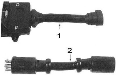
1 - for docking a Brylite plug to a Utilux socket
2 - for docking a 6-pin Utilux plug to a 5-pin Utilux socket
Installing the tow bar
Note. To equip a tow hitch with a tow hitch receptacle, (at a minimum): Receptacle matching the trailer plug, support bracket, 7-wire flexible cable, insulated wire connectors and rubber grommet.
Necessary components for trailer power equipment using a Utilux towbar connector
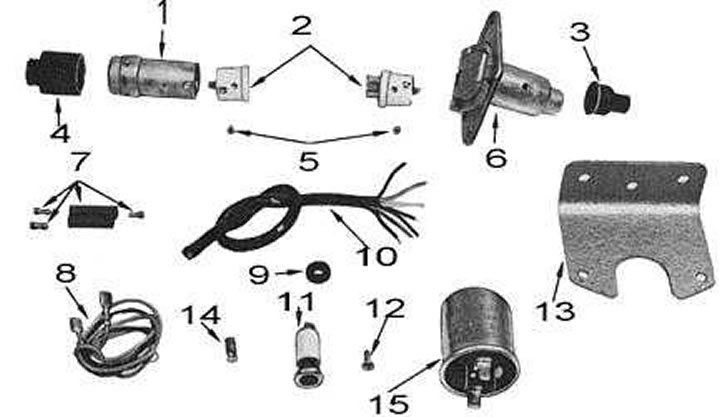
1 - plug; 2 - terminal blocks; 3 - anther; 4 - anther; 5 - screws; 6 - nest; 7 - connector for connecting wires; 8 - wire; 9 - bushing,; 10 - 7 - core flexible cable; 11 - control repeater; 12 - screw; 13 - support bracket; 14 - lamp
1. Disconnect the negative cable from the battery.
2. Locate the lamp harness at the rear of the vehicle.
3. Locate the power wires for the right and left rear direction indicators, tail lights, brake lights, reversing lights and ground. Using the wiring diagrams given at the end of this Chapter, determine the color marking of each of the listed wires.
4. Using insulated connectors, connect a 7-wire flexible cable to each of the found wires.
5. If using a 7-pin towbar connector, follow the standard color coding scheme as follows:
| terminal no | Circuit | Color |
| 1 | Left Turn Signal Lamp | Yellow |
| 2 | Reversing lamp | Black |
| 3 | Weight | White |
| 4 | Right Turn Signal Lamp | Green |
| 5 | Electric brakes | Blue |
| 6 | Stop lamp | Red |
| 7 | side light lamp | Brown |
6. If using a 6-pin type towbar connector, follow the standard color coding scheme as follows:
| terminal no | Circuit | Color |
| 1 | side light lamp | Brown |
| 2 | Left Turn Signal Lamp | Yellow |
| 3 | Right Turn Signal Lamp | Green |
| 4 | Stop lamp | Red |
| 5 | Auxiliary circuit | Blue |
| 6 | Weight | White |
7. If using a 5-pin towbar type, follow the standard color coding scheme as follows:
| terminal no | Circuit | Color |
| 1 | Left Turn Signal Lamp | Yellow |
| 2 | Weight | White |
| 3 | Right Turn Signal Lamp | Green |
| 4 | Stop lamp | Red |
| 5 | side light lamp | Brown |
8. Drill a suitable hole in the vehicle floor panel and install the rubber grommet in it.
Note. Before drilling a hole, check whether any of the existing technological ones can be used. The bushing must be installed without fail to avoid rubbing the wires.
9. Insert a 7-core flexible cable into the hole with the grommet installed.
10. Cut the cable to the required length and fit the dust boot over it.
11. Strip each of the wires of the cable from the insulation by approximately 15 mm.
12. Connect the cable strands to the receptacle terminals using the standard color scheme and following the connector manufacturers' instructions.
13. Assemble the nest and install the boot on its rear end. The components of the Brylite 7-pin towbar connector are shown in the accompanying illustration.
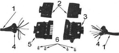
1-7 - core flexible cable; 2 - covers; 3 - nest; 4 - anther; 5 - plug; 6 - screws
14. Mount the support bracket as close as possible to the hitch ball stud and high enough to maintain the vehicle's ground clearance.
15. Install the connector receptacle into the bracket.
16. Connect the trailer's plug to the tow bar's receptacle to check that they are properly mated.
Installing the trailer plug
Note. To equip a trailer with a tow bar connector, (at a minimum): plug, 7-wire flexible cable and insulated connectors for connecting wires, matching the vehicle connector socket.
The procedure for installing a plug on a trailer is the same as for installing a connector receptacle on a vehicle, subject to the following points.
1. Connect the trailer wiring to the connector plug in accordance with the generally accepted color coding standard. Follow the connector manufacturers' instructions. If the free length of the trailer wiring harness is insufficient, extend the wiring harness with a 7-wire flexible cable and insulated wire connectors.
2. If the color scheme of the trailer wiring does not correspond to the generally accepted standard, identify each of the wires, for which:
- Find the trailer ground wire;
- Connect the jumper wire from the negative terminal of the 12-volt battery to the ground wire;
- Connect a jumper wire to the positive battery terminal and connect each of the trailer harness wires to it in turn. Record the color of each wire and the device triggered when connected (signal light/brake).
3. After installation is complete, connect the plug to the tow bar receptacle on the vehicle to check that the connector components are properly mated.