


Table of contents: How to make a test lamp ↓ How to Make a Jumper Wire ↓ Checking the serviceability of…↓ Checking the lamps for proper…↓
How to make a test lamp
Incandescent test lamp
When servicing electrical systems, a test lamp is the most effective tool for checking for continuity in a circuit under load.
The simplest probe lamp can be made from a pair of pieces of 4-mm wire, a pair of crocodile clips and a cartridge equipped with two contacts and a 1-thread lamp designed for a supply voltage of 12 V with a 2-pin base (see accompanying illustration).
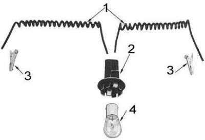
1 - wires; 2 - cartridge; 3 - clamp; 4 - lamp
1. Strip the wires at both ends to a convenient length.
2. Solder alligator clips to one end of each wire.
3. Connect the opposite ends of the wires to the terminals of the cartridge, making sure that they do not touch each other or the body of the cartridge.
4. Install the lamp with the base into the socket.
5. To check the proper functioning of the assembly, connect the clamps to the terminals of a 12-volt battery. The lamp should light up.
LED test lamp
Using a normal type test lamp (with filament) to check the presence of conductivity in circuits that include electronic components, such components may fail due to a sufficiently high current flowing through them. The authors of this Manual recommend using a light-emitting diode (LED) probe lamp in such cases.
A simple LED test lamp can be made from a piece of 3mm wire of the appropriate length, an alligator clip, an LED, and a 1/4W, 560 Ohm resistor. You will also need a casing, which is fairly easy to make from an old ballpoint pen and a thin metal rod (piece of wire), pointed at one end. Make sure that the connection of the anode and cathode of the LED is made exactly as shown in the illustration.
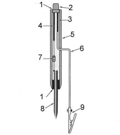
1 - glue; 2 - LED; 3 - diode cathode; 4 - diode anode; 5 - body of the pen; 6 - wire; 7 - resistor; 8 - feeler gauge (pointed metal rod); 9 - clamp
Note: When using a LED test lamp, remember that the diode only allows current to flow in one direction, so the lamp will only function if the wire clamp is connected to the negative side of the circuit and the probe to the positive side.
1. Solder a piece of wire to the cathode of the LED (the cathode terminal is noticeably shorter than the anode terminal located next to it on the end of the diode).
2. Solder a 560 Ohm resistor to the anode.
3. Solder a short piece of wire between the resistor and the probe.
4. Drill a hole in the wall of the pen body and pass the wire coming from the cathode through it.
5. Using glue, secure the probe into the body of the pen by pushing its end into the bottom hole.
6. Solder a crocodile clip to the cathode wire released through the side hole.
7. The LED can be fixed in a plug that fits tightly into the top hole of the pen body. To observe the diode, a viewing hole must be made in the plug.
How to Make a Jumper Wire
When diagnosing faults in electrical system components, it can be very useful to have a jumper wire on hand.
1. Strip a suitable length of 4mm wire from both ends.
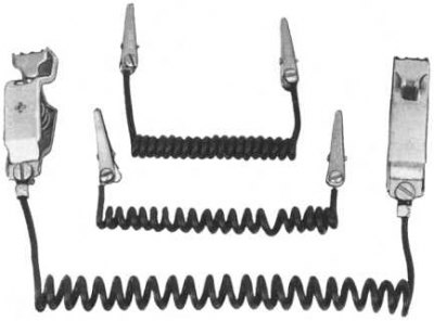
2. Connect "crocodile" clips to both ends of the wire (solder them or secure them to the terminals with screws). Examples of jumper wires of various lengths are shown in the accompanying illustration.
3. Check the jumper wire for conductivity by disconnecting one of the wires from the battery and connecting the jumper wire between the battery terminal and the tip of the wire. Turn on the ignition - the control lamps on the instrument panel should light up properly.
4. Remove the jumper wire and restore the original battery connection.
Note: It is best to make several jumper wires in advance, of different lengths and with different types of clamps.
Checking the serviceability of switches
If you have any doubts about the proper functioning of the switch, disconnect the wiring from it and use a test lamp to check for power. If the switch is included in the ignition circuit, you will have to turn the key to the ON position to check.
Once you have determined the color and location of the power wire, disconnect the test lamp from it, take a suitable jumper wire and connect it between the power wire of the switch and the wire on the opposite side. If the circuit is OK, the switch should be replaced.
Checking the lamps for proper operation
If you suspect a bulb is bad, remove it from its socket, then connect one end of a small jumper wire to the positive terminal of a good battery and the other end to the tab on the wall of the bulb base.
Connect one end of the second jumper wire to the negative terminal of the battery, and press the other end to the lamp contact. The working lamp should light up.
If the lamp has two filaments, press the end of the jumper wire to the second contact of the lamp. The lamp should also light. The faulty lamp should be replaced with one that is adequate in terms of power consumption and nominal supply voltage.
Checking the electrical circuit for proper operation
If you suspect that an electrical circuit is failing, apply voltage to it by turning on the appropriate switches and toggle switches.
Disconnect any of the terminals of the circuit and connect one of the test lamp wires to the power, or switch-facing, side of the de-energized circuit. Connect the other test lamp wire to the vehicle ground (any screw or bolt on the chassis, body or engine block). If the lamp does not light, check the circuit closest to the power source or switch.
If the lamp lights up, continue testing, moving towards the electrical consumer (motors, lamps, etc.).
Note: The best place to start testing the circuit is at the fuse terminal. Remember to reconnect the previous connector/terminal connection each time you move to the next section of the circuit.