AT RE4F02A internal components layout diagram
Tightening force of threaded connections, Nm:
- A: 44 ÷ 5
- V: 6.3 ÷ 8.3
- C and N: See subsection "Assembly"
- D: 20 ÷ 26
- E: 5 ÷ 7
- F: 6.3 ÷ 6.8
- G: 74 ÷ 88
- H, J, and K: 16 ÷ 21
- I: 31 ÷ 37
- L: 7 ÷ 9/3.7 ÷ 5.0
- M and O: 5 ÷ 7
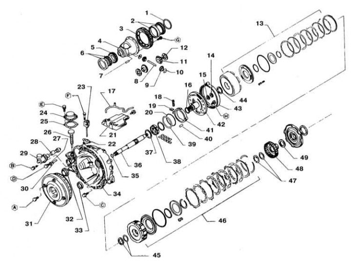
1 - Gasket for adjusting the bearing preload; 2 - Bearing; 3 - Driven gear of the main gear; 4 - Differential box; 5 - Drive gear of the regulator shaft; 6 - Bearing; 7 - Locking pin; 8 - Axis of satellites; 9 - Satellite; 10 - Thrust washer; 11 - Differential side gear; 12 - Washer; 13 - Reverse clutch assembly; 14 - Bearing cage; 15 - Needle bearing; 16 - Rotor support ring; 17 - Differential lubrication supply pipe; 18 - Return spring; 19 - Spring holder; 20 - Ring; 21 - Mesh oil filter; 22 - Gasket; 23 - Control cylinder; 24 - Regulator cover; 25 - Gasket; 26 - Axis of the regulator; 27 - Sealing washer; 28 - Speedometer drive; 29 - Speedometer drive housing; 30 - Pin; 31 - Rotation converter; 32 - stuffing box; 33 - Oil seal; 34 - Housing of the rotation converter (transmission dome); 35 - O-ring; 36 - Primary shaft; 37 - Ring; 38 - Rotor; 39 - Friction ring; 40 - Articulated pin; 41 - Stator ring; 42 - Oil pump cover; 43 - Brake tape; 44 - Washer; 45 - Needle bearing; 46 - Assembling the overdrive clutch; 47 - Needle bearing; 48 - Overdrive clutch hub; 49 - Needle bearing
AT RE4F02A internal components layout diagram (continuation)
Tightening force of threaded connections, Nm:
- A: 44 ÷ 5
- V: 6.3 ÷ 8.3
- C and N: See subsection "Assembly"
- D: 20 ÷ 26
- E: 5 ÷ 7
- F: 6.3 ÷ 6.8
- G: 74 ÷ 88
- H, J, and K: 16 ÷ 21
- I: 31 ÷ 37
- L: 7 ÷ 9/3.7 ÷ 5.0
- M and O: 5 ÷ 7
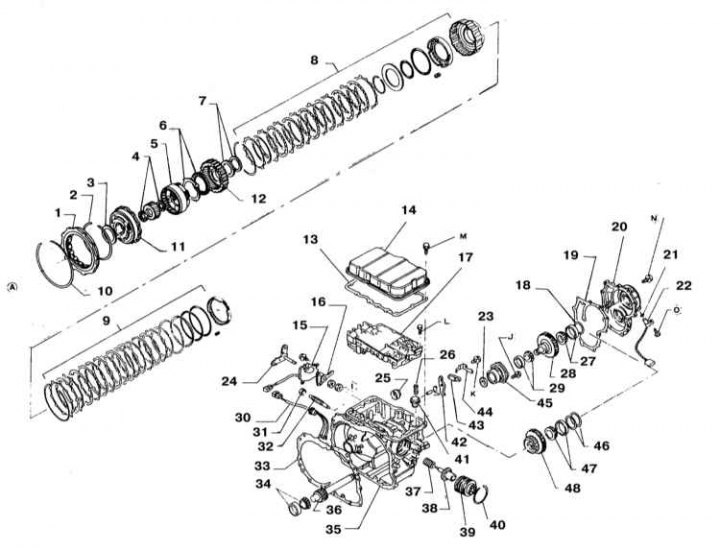
1 - overrunning clutch; 2 - Thrust ring; 3 - Needle bearing; 4 - Needle bearing; 5 - Rear fastener; 6 - Needle bearings; 7 - Needle bearing; 8 - Assembling the low gear clutch; 9 - Brake assembly of low and reverse gears; 10 - Thrust ring; 11 - Front fastener; 12 - Rear internal gear; 13 - Sealing gasket; 14 - Valve assembly cover; 15 - Sensor-switch for launch permission; 16 - Plate; 17 - Assembly of control valves; 18 - Adjusting washer of the driven shaft bearing; 19 - Sealing gasket; 20 - Side cover; 21 - O-ring; 22 - Speed sensor; 23 - Needle bearing; 24 - Manual shift lever; 25 - Oil seal; 26 - Spring; 27 - Bearing; 28 - Driven shaft; 29 - Bearing; 30 - Terminal; 31 - Locknut; 32 - Anchor pin; 33 - Sealing gasket; 34 - Bearing; 35 - Carter AT; 36 - Gear reducer; 37 - Return spring; 38 - Servo piston; 39 - Servo; 40 - Thrust ring; 41 - Damper; 42 - Parking latch; 43 - Latch gasket; 44 - Parking stopper; 45 - Bearing retainer; 46 - Adjusting washers of the intermediate gear axle bearing; 47 - Bearing; 48 - Intermediate gear
The layout of the oil flows in the crankcase AT
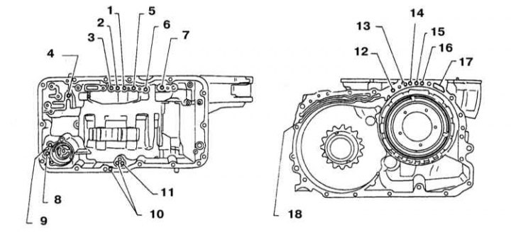
1 - Torque converter output pressure; 2 - Reverse clutch pressure; 3 - Overdrive clutch pressure; 4 - Servo pressure; 5 - Torque converter locking pressure; 6 - Oil pump backpressure; 7 - Pressure in the pipeline; 8 - Low clutch release pressure; 9 - Pressure in the pipeline; 10 - Low clutch pressure; 11 - Brake pressure of low and reverse gears; 12 - Oil pump backpressure; 13 - Locking pressure of the torque converter; 14 - Torque converter output pressure; 15 - Reverse clutch pressure; 16 - Overdrive clutch pressure; 17 - Pressure in the pipeline; 18 - Pressure in the pipeline
The layout of the oil flows in the housing of the rotation converter
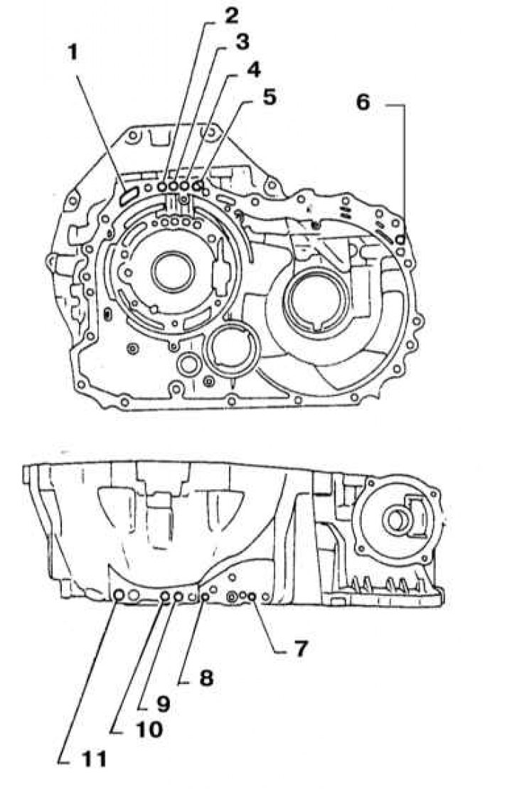
1 - Pressure in the pipeline; 2 - Overdrive clutch pressure; 3 - Reverse clutch pressure; 4 - Inlet pressure of the torque converter; 5 - Torque converter locking pressure; 6 - Pressure in the pipeline; 7 - Back pressure; 8 - Locking pressure; 9 - Reverse clutch pressure; 10 - Overdrive clutch pressure; 11 - Pressure in the pipeline
The layout of the oil flows in the cover of the oil pump
1 - Overdrive clutch pressure; 2 - Reverse clutch pressure; 3 - Inlet pressure of the torque converter; 4 - Locking pressure of the torque converter; 5 - Reverse clutch pressure; 6 - Overdrive clutch pressure; 7 - Pressure side of the oil pump; 8 - Suction side of the pump; 9 - Torque converter output pressure
General information
The compilers of this Guide do not recommend car owners to undertake the overhaul of AT on their own. During the disassembly and assembly procedures, the transmission has to remove and then reinstall many small components. It is necessary to make a lot of accurate measurements and, by selecting shims, rings and spacers, clearly set a lot of gaps. In view of the foregoing, it would be wiser to entrust the overhaul of AT to car service specialists. Note that in many cases it is possible to purchase a refurbished unit on an exchange basis, which is often cheaper than a complex repair.
Despite the foregoing, the independent repair of AT by an amateur mechanic is not at all an absolutely impossible undertaking. Indispensable conditions are only the availability of the necessary special tools and accuracy in the approach to the implementation of all procedures.
Tools needed to rebuild an AT include needle nose pliers for removing inner and outer circlips, a bearing puller, a sliding hammer, a set of drifts and center punches, a DTI gauge, and possibly a hydraulic press. In addition, of course, you will need a durable, vise-equipped workbench, or a special assembly stand.
In the course of performing the disassembly procedures for the AT, try to remember, or rather write down, the installation order of each of the parts to be removed.
Before proceeding with the disassembly of the transmission, it would be wise to try to analyze the symptoms of its failures in order to approximately determine their causes. Many failures are uniquely related to the failure of well-defined components. See also the AT Troubleshooting Section at the beginning of the Guide.
The following subsection provides a schematic description of the procedure for disassembling the AT and servicing its internal components.
Dismantling, maintenance of internal components of the AT
1. The illustrations show the layout of the internal components of the AT and the operation of the hydraulic system.
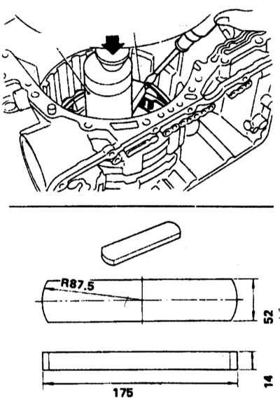
2. Drain the ATF (see chapter Settings and ongoing maintenance).
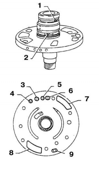
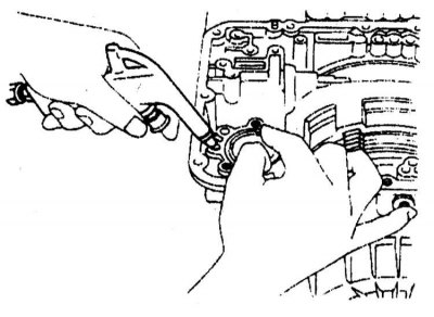
3. Remove the rotation transducer.
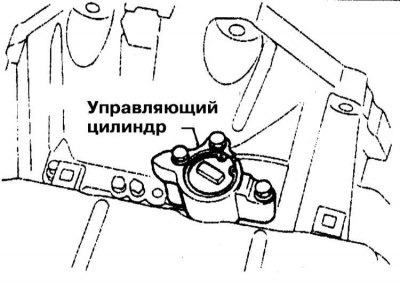
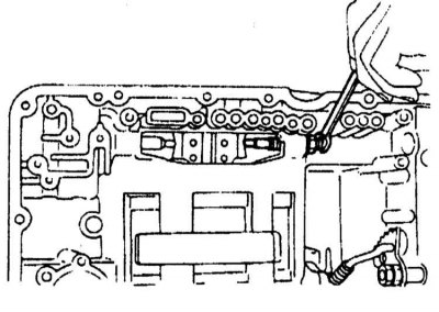
4. Remove the control cylinder.
5. Remove the valve assembly cover.
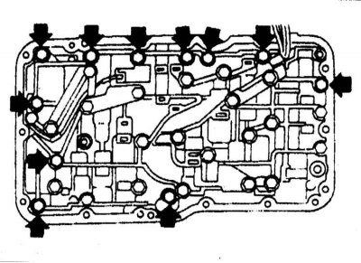
6. Disconnect the electrical wiring from the control valve and remove the valve assembly
7. Disconnect the terminal harness.
Note. The harness is routed deep enough to catch when pulled - try not to use excessive force. When pulling, bend the tourniquet inward and push it outward. Do not pull the assembly by the wire.
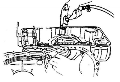
8. Remove the accumulator.
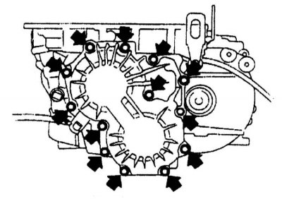
9. Remove the side cover.
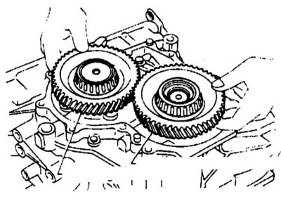
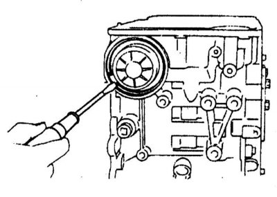
10. Remove the output gear.
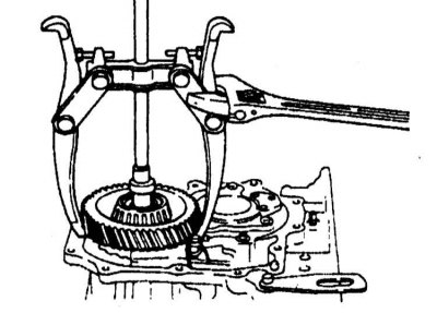
11. Using a puller, remove the intermediate gear.
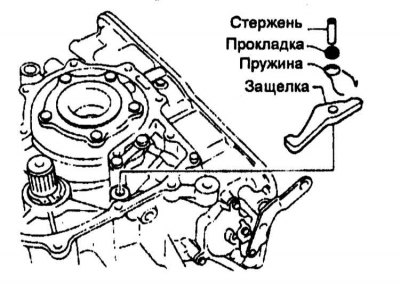
12. Remove the parking latch, return spring, and gasketed pin.
13. Remove the speedometer drive components.
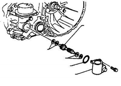
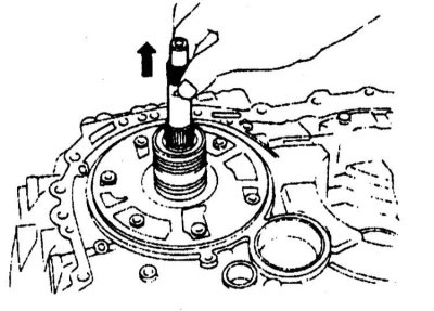
14. Remove the governor shaft.
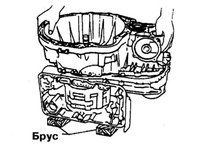
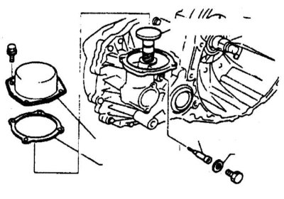
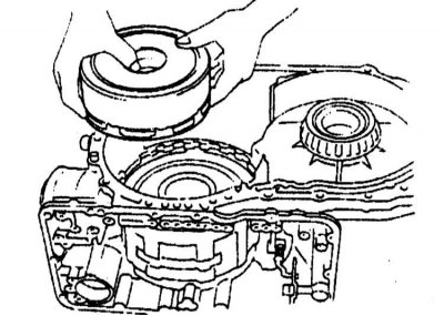
15. Establish assembly АТ on a bar and remove a casing of the converter of rotation.
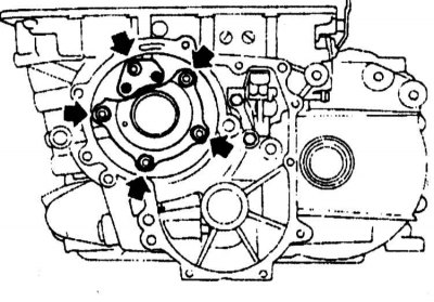
16. Remove assembly of the main transfer.
17. After removing the O-ring, remove the input shaft from the converter housing.
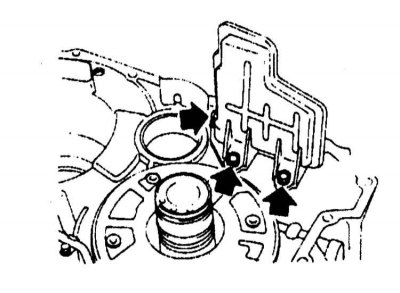
18. Remove the mesh oil filter.
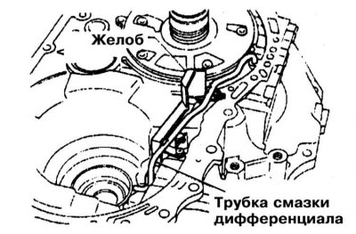
19. Remove the differential grease supply tube.
20. Loosen the band brake pin nut, then unscrew the pin from the piston.
21. Remove the brake band, remove the overdrive clutch and reverse clutch assembly.
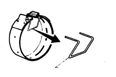
22. To prevent damage to the drum brake linings, be careful not to overstretch the flexible strip. When removing the brake band, hold it by the bracket. After removing the tape, lower the bracket to its original position.
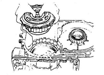
23. Remove the freewheel, front fastener, rear fastener, and underdrive clutch.
24. Remove the low and reverse clutches, disconnect the low and reverse brake retainer thrust ring.
25. By supplying compressed air, remove the towing and reverse gear brake piston.
26. Remove the separator assembly.
27. Remove the thrust ring of the servomotor.
28. Remove the band brake servomotor and return spring.
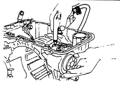
29. Loosen the lock nuts on the manual shaft and remove the manual drive plate.
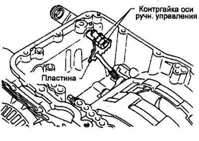
30. Remove the pin and remove the manual control shaft.