


Clutch assembly components
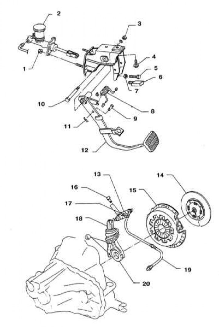
1 - Nut (8÷11 Nm); 2 - Master cylinder; 3 - Nut (16÷22 Nm); 4 - Pedal support bracket mounting bolt; 5 - Pedal stop mounting bolt; 6 - Starter circuit breaker switch (12÷15 Nm); 7 - Nut of the fastening bolt (16÷22 Nm); 8 - Return spring; 9 - Pin; 10 - Pedal axle; 11 - Cotter pin; 12 - clutch pedal; 13 - Executive cylinder; 14 - Slave disk; 15 - Clutch basket assembly (pressure plate); 16 - Bolt (30÷40 Nm); 17 - Air valve (6÷10 Nm); 18 - Clutch release lever; 19 - Hydraulic hose; 20 - Release bearing
All models equipped with a manual transmission use a single-plate dry clutch with a diaphragm spring. The hub of the friction (slave) clutch disk is equipped with longitudinal splines that engage with the splines of the transmission primary shaft journal. The friction and pressure plates of the clutch are held in contact with each other by the force developed by the diaphragm spring of the pressure plate.
The clutch is released hydraulically. The release drive consists of a clutch pedal, a main hydraulic cylinder equipped with a reservoir, connecting lines and an actuator cylinder that acts on the clutch release lever, and a release bearing.
When the pedal is depressed, the hydraulic pressure in the system tract rises, the resulting effect of which is applied to the outer end of the clutch release lever. When the lever is turned, the fingers of its shaft rest against the release bearing, which, in turn, shifts, pressing against the petals of the diaphragm spring of the pressure plate in the clutch basket. Bending, the spring interrupts the contact of the pressure and driven disks, releasing the latter.
When servicing the clutch, in addition to replacing components that have obvious mechanical damage, it is necessary to carry out some initial checks (it is assumed that the gearbox is in good condition):
- a) First of all, make sure that the free travel and the height of the clutch pedal are adjusted correctly - make the appropriate adjustments if necessary (see section Adjusting the clutch pedal).
- b) Check the fluid level in the clutch master cylinder reservoir (see Chapter Settings and ongoing maintenance). If necessary, make adjustments by adding the required amount of hydraulic fluid and carefully inspect the system for signs of leaks (see sections Removal and installation the clutch master cylinder and Removal and installation the clutch slave cylinder). When emptying the master cylinder reservoir, it is necessary to remove air locks from the hydraulic circuit (see section Bleeding air from the hydraulic circuit of the clutch release drive), then check the proper functioning of the clutch;
- c) To assess the clutch shift time, start the engine at normal idle speed. Make sure that the gear is in neutral and release the clutch pedal. Now depress the clutch pedal and, after waiting a few seconds, engage reverse gear. The shift should not cause grinding or other extraneous noises, which most likely indicate a faulty driven disc or clutch basket assembly;
- d) To check that the clutch is fully disengaged, apply the parking brake and start the engine. Keeping the clutch pedal about 13 mm above the floor, shift the transmission between first and reverse gears. If there is any interference when shifting the lever, this indicates a faulty clutch release mechanism component. Estimate the stroke of the clutch slave cylinder pusher. When the pedal is fully depressed, the pusher should extend noticeably, otherwise, check the hydraulic fluid level in the master cylinder;
- e) Perform a visual inspection of the condition of the axle bushings at the top of the clutch pedal. Make sure there are no signs of jamming or excessive play in the axle;
- f) After getting under the vehicle, make sure that the clutch release lever is securely seated on the ball pin of the spherical support.
[See the original on the resource: nissanbook]