


2. Remove the heated oxygen sensor 1 wiring harness bracket from the cylinder head.
3. Remove the exhaust manifold cover.
4. Using a special key (KV10117100) (A) Remove heated oxygen sensor 1.
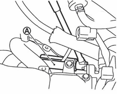
Caution: Be careful when handling the heated oxygen sensor 1 and do not subject it to impacts.
Note: The exhaust manifold can be removed and installed without removing the heated oxygen sensor 1 (in this case, you still need to disconnect the wire connector).
5. Loosen the exhaust manifold support mounting bolt from the exhaust manifold side.
6. Unscrew the mounting nuts from the edges to the middle and remove the exhaust manifold.
7. Remove the gasket.
Caution: Cover engine openings to prevent foreign material from entering.
8. Remove the exhaust manifold cover from the back of the exhaust manifold.
9. Installation is carried out in the reverse order of removal, taking into account the following:
Tighten the nuts in the sequence shown in the figure.
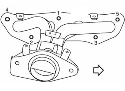
Engine HR16DE
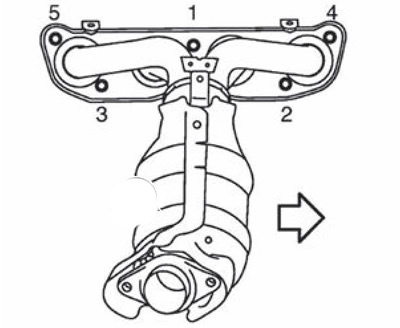
Engine HR20DE
Note: The arrow in the figure shows the front of the engine.
Check after removal
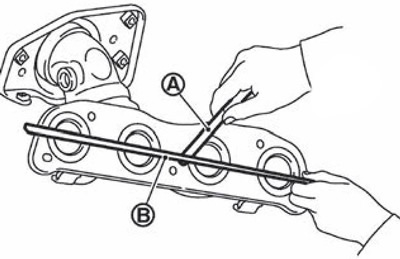
Using a straightedge (B) and a set of flat feeler gauges (A), check the deformation of the contact surface of the exhaust manifold. If the obtained value exceeds the norm, replace the exhaust manifold with a new one.
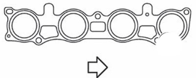
Note: MR20DE engine: Install the cylinder head gasket as shown in the figure.
Install the exhaust manifold stand (2) in the direction shown in the figure.
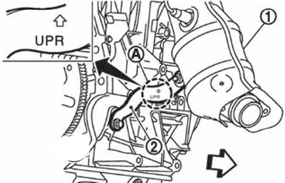
1. Exhaust manifold.
A. Upper mark.
The arrow points to the front of the engine.
Note: This figure shows the 2WD version as an example.