


The bearing design provides significant ease of maintenance, since preload is created simply by tightening the hub nut to the specified tightening torque. On vehicles with an ABS system, a wheel speed sensor rotor is installed on the rear hub.
Removal
- Raise the rear of the vehicle.
- Remove the wheel.
- Remove the brake caliper. Do not disconnect the brake hose from the caliper. Using wire, tie the caliper to the body, making sure that the brake hose is not too tight.
Caution: When the brake caliper is removed, do not press the brake pedal.
- Place alignment marks (arrow) on the brake disc and wheel hub with bearing, then remove the brake disc.
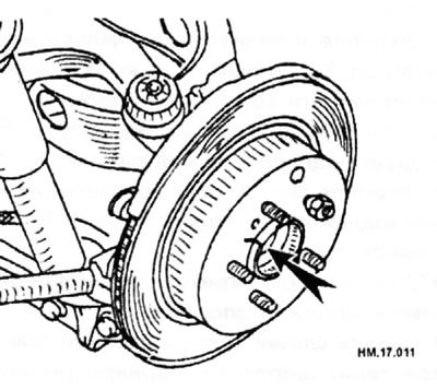
- Remove the wheel speed sensor from the hub support.
Caution: Do not pull on the wheel speed sensor wiring harness.
Caution: Do not allow any damage or even scratches to the teeth of the wheel speed sensor rotor. Do not drop the sensor. If, as a result of rotor deformation, a part of a rotor tooth breaks off, this will lead to the inability to correctly determine the wheel speed and will disrupt the functioning of the ABS system as a whole.
- Remove the parking brake cable and parking brake shoes from the rear plate.
- All-wheel drive models: remove the cotter pin, unscrew the nut from the drive shaft, unscrew the wheel hub mounting bolts and, using a suitable puller, remove the wheel hub with bearing from the drive shaft.
Caution: When removing the hub, do not tilt the drive shaft joints at large angles. Be careful not to stretch the inner hinge too much. Do not allow the drive shaft to hang without support for the hinges and other parts.
- Two-wheel drive models: Remove the wheel hub and bearing mounting bolts, then remove the wheel hub and bearing.
Caution: The rear wheel hub bearing assembly cannot be disassembled. If the inner bearing race remains in place when the hub assembly is removed, the hub must always be replaced with a new one as a whole, otherwise damage to the seal may cause grease leaks or increased runout.
- Replace the rear wheel hub assembly if the inner bearing race is worn.
- Loosen the bolts and nuts securing the lower front link, torque rod and lower rear link to the rear suspension beam.
- Unscrew the lower shock absorber mounting bolt, the bolt and nut of the lower front link mounting on the hub support side. In this case, the lower rear rod must be supported with a jack.
- Remove the bolt and nut securing the lower rear link to the hub support. Then remove the spring.
- Remove the bolt and nut securing the reaction rod to the hub support.
- Remove the cotter pin and then loosen the control arm ball joint retaining nut.
- Using a suitable ball joint puller, separate the control arm from the hub support. Be careful not to damage the ball joint boots.
Caution: To prevent damage to the threads and unexpected slipping of the puller, do not completely unscrew the fastening nut.
- Remove the hub support from the vehicle.
- Remove the anchor support mounting nuts, then remove the anchor support and back plate from the hub support.
- 2WD models: Remove the hub cap.
- 4WD models: Remove the dust cover from the hub carrier.
Examination
- Check the hub components for cracks and damage.
- Check the hub seal for cracks or damage.
- Check the hub bearing for wear or damage.
- Check for chips on the teeth of the wheel speed sensor.
Installation
- Installation is carried out in the reverse order of removal, taking into account the following.
- Always install new cotter pins.
- Tighten the hub support mounting bolts and nuts to a torque of 50-70 Nm.
- Tighten the bushing mounting nuts to a torque of 95-1 15 N·m.
- Tighten the drive shaft nut to a torque of 100-150 Nm.
- When installing the brake disc and wheel hub with bearing, align the alignment marks made during removal.
- Lower the vehicle and perform the final tightening of the suspension rod fastening parts with rubber bushings on an unloaded vehicle.
- After installation, check the wheel alignment angles.
Wheel hub components

1 — cotter pin (all-wheel drive models); 2 - brake disc; 3 - anchor support; 4 - wheel hub with bearing; 5 - back plate; 6 — bushing; 7 — hub support; 8 — hub support cap (2-wheel drive models), dust cover (all-wheel drive models); 9 - nut (all-wheel drive models).