- Remove the oil pump cover.
- Remove both gears from the oil pump bore.
- After removing the plug, pull out the pressure reducing valve together with the spring.
- Clean all parts thoroughly and check as follows:
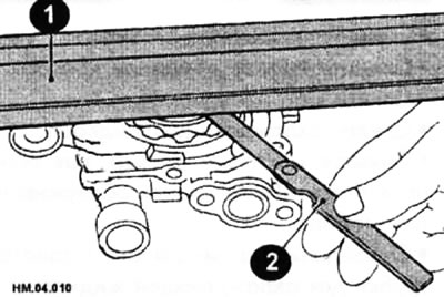
- Insert both gears into the pump and measure the axial clearance between the top of the pump housing and the top of the gears by applying a steel ruler (1) and measuring with a feeler gauge (2) as shown in the figure.
- The maximum allowable clearance is 0.070 mm between the ruler and the internal gear and 0.11 mm between the ruler and the external gear. If necessary, the gap can be reduced somewhat by grinding the surface of the pump body with abrasive materials on a straightening plate.
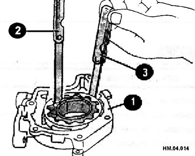
- Insert a narrow feeler gauge (3) between the outside of the outer gear and the housing bore (1). The gap should not exceed 0.26 mm. The procedure for performing this measurement is shown in the figure. This figure also shows the measurement of the gap between adjacent teeth (2). This gap should be no more than 0.18 mm.
- Calculate the clearance between the seating surfaces of the internal gear and the oil pump housing as follows:
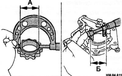
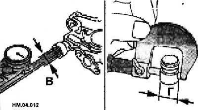
♦ Using a bore gauge, measure the inner diameter of the oil pump housing (B).
♦ Measure the outside diameter of the protruding portion of the internal gear (A).
♦ The gap is equal to the difference between the internal diameter of the oil pump housing and the external diameter of the protruding section of the internal gear and should be within 0.045-0.091 mm.
- Check the relief valve clearance:
Oil pump components
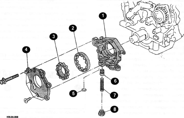
1 — oil pump housing; 2 - external gear; 3 - internal gear; 4 — oil pump cover; 5 - sealing ring; 6 — pressure reducing valve; 7 - spring;8 — pressure reducing valve plug.
♦ Measure the outside diameter of the pressure reducing valve (G).
♦ The clearance of the adjusting valve is equal to the difference between the diameter of the valve hole and the outer diameter of the valve and should be within 0.040-0.097 mm.
- If the measured values exceed the wear limits, either the pump gears or the camshaft drive cover must be replaced.
- The oil pump is assembled in the reverse order of disassembly.
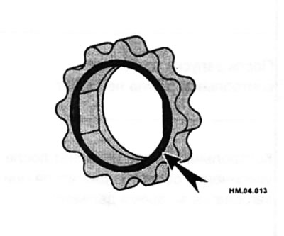
- Install the internal gear so that the groove (arrow) faces the oil pump cover.
- Before installing the cover, lubricate the gears well so that the pump does not jam when starting the engine.
- Tighten the self-tapping screws to a torque of 5.9-7.9 N·m, and the cover mounting bolts to a torque of 6.97-7.45 N·m.
- Lubricate the pressure relief valve with engine oil. Check that the valve drops evenly into the valve hole under its own weight. Screw in the plug with a new gasket and tighten to a torque of 39.2-68.7 Nm.
Read more on the website (nissanbook)