


2. Loosen the lock nut of the gearbox shaft adjusting screw and unscrew the gearbox cover bolts (photo).
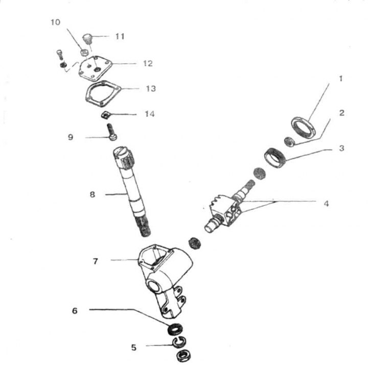
16.2 Steering gear parts
1, 10. Lock nut; 2, 6 Seal; 3. Adjusting nut; 4. Ball nut and drive shaft of the gearbox; 5. Spring washer; 7. Body; 8. Bipod shaft; 9. Adjusting screw; 11. Cork; 12. Lid; 13. Gasket; 14. Regulator
3. Turn the adjusting screw clockwise and remove the cover.
4. Remove the bipod shaft and take out the adjusting screw.
5. Using a special key, unscrew the adjusting nut (photo).
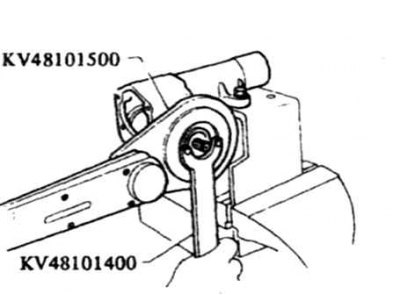
16.5 Unscrewing the gearbox adjusting nut
6. Remove the drive shaft of the gearbox together with the adjusting nut (photo).
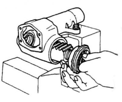
16.6 Removing the gearbox drive shaft together with the adjusting nut
Caution! Do not allow the balls to move toward the ends of the worm thread. Otherwise, the worm part of the shaft will be damaged. In case of wear or damage, the ball nut and worm should be replaced.
7. The needle bearings of the pitman shaft must not be removed. If the bearings are worn out, replace the entire gearbox.
8. Unscrew the adjusting nut and knock the seal off the nut.
9. Pry and remove the seal from the gearbox housing.
10. Wash all parts.
11. Inspect the teeth on the pitman shaft, check for cracks or burrs.
12. Check the condition of the pitman arm shaft splines.
13. Check the condition of the threads on the drive shaft, the presence of cracks, burrs and other damage. Check the freedom of rotation of the ball nut on the worm. Check the freedom of movement of the balls by gradually turning the shaft to a vertical position, the balls should roll off under their own weight. Otherwise, replace the drive shaft.
Caution! When checking, do not allow the ball to roll to the very end of the worm gear tooth.
14. Check the freedom of rotation of the gearbox bearings. If jammed, replace the bearing assembly with the outer race.
15. Before assembly, lubricate all parts. Install new seals so that the side with the letters faces outward. Fill the seals with grease.
16. Install the new seal onto the adjusting nut.
17. Install the drive shaft assembly with the nut into the gearbox. Screw the nut onto the thread in the gearbox.
18. Create a preload in the bearings of the gearbox input shaft (photo). To do this, gradually tighten the adjusting nut until the moment of resistance to shaft rotation becomes equal to that specified in the Technical Data.
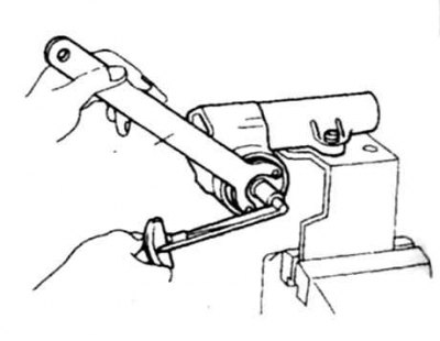
16.18 Creating a preload in the steering gear drive shaft bearings
The torque is measured with a torque wrench with a scale of several Nm after turning the drive shaft in both directions for several revolutions. To improve the engagement of the splines with the key, insert a piece of plastic card into the head of the key.
19. Lubricate the ring lock nut with locking compound and use it to tighten the adjusting nut, without allowing the adjusting nut to turn. Check the preload in the bearings again.
20. Install the adjusting screw into the T-shaped cutout of the bipod shaft and check the axial clearance of the screw in the cutout (photo). Compensate this clearance to the norm by selecting an adjusting washer according to the thickness (see Technical data).
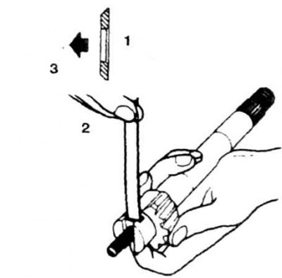
16.20 Checking the axial clearance of the pitman shaft
1. Adjusting washer; 2. Play in the knuckle shaft; 3. Towards the gearbox cover
21. Install a new seal into the steering gear housing tailpiece.
22. Turning the adjusting screw counterclockwise, install the housing cover on the shaft, screw on the lock nut (photo).
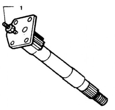
16.22 Before installing the cover on the shaft, tighten the screw by turning it counterclockwise
23. Install the gasket on the cover, lubricating both sides with sealant.
24. Turn the drive shaft by hand and set the ball nut to the middle position. Install the pitman arm shaft with the screw. Make sure that the center tooth on the pitman arm shaft engages with the center groove of the ball nut. Do not damage the seal lips when performing this procedure.
25. Tighten the cover bolts to the specified torque.
26. Pour oil into the gearbox and tighten the plug.
27. Create a preload in the pitman shaft bearings by turning the adjusting screw (photo). The resistance to turning the pitman shaft should correspond to that specified in the Technical Data. The torque is checked with the pitman shaft in the straight-ahead position.
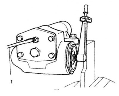
16.27 Check the moment of resistance to turning of the bipod shaft by gradually rotating the adjusting screw
1. Screwdriver
28. Tighten the lock nut and check the tension again.