


Pre-injection system
1. Perform decompression and remove the valve body.
2. Remove the gasket and wiring seal from the housing (photo).
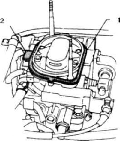
13.2 Gasket and seal for injector wires
1. Gasket; 2. Seal
3. Remove the nozzle cover (photo).
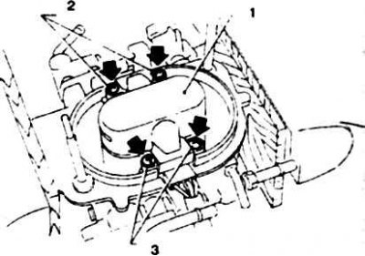
13.3 Nozzle cover screws
1. Lid; 2.3. Screws
4. Open the valve and carefully knock out the nozzle by hitting it with a mandrel with an internal diameter of at least 5.4 mm (photo). Do not damage the nozzle.
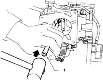
13.4a Removing the injector
1. Mandrel
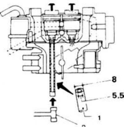
13.4b Mandrel dimensions (outside brackets in mm) and a diagram of its location when knocking out the injector
1. Mandrel; 2. Plastic hammer; 3. Dimensions in mm
5. If only the sealing rings are being changed, replace the small and large rubber rings, lubricating them with silicone grease. Install the injector (photo).
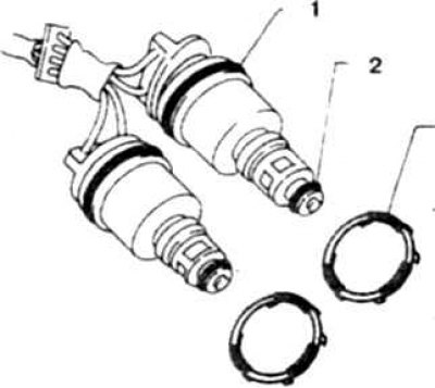
13.5 Always replace the sealing rings when removing the injectors
1. Big ring; 2. Small ring; 3. Rubber ring
6. If you are replacing a faulty injector, remove the wire lead of the faulty injector from the connector, for which do the following:
- a), remove the output retainer (photo),
- b), use a thin screwdriver to push the tab away and immediately push out the terminal, do not pull on the wire (photo),
- c), cut the wire directly at the bushing (photo), having first identified the required wire according to the diagram (photo).
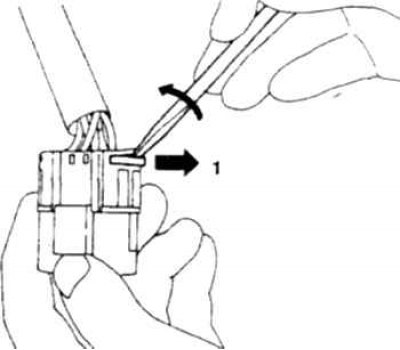
13.6a To disconnect the terminal from the connector, remove the holder
1. Push out
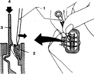
13.6b Pull the tab aside and push the terminal out
1. Screwdriver; 2. Tongue; 3. Conclusion; 4. Push out
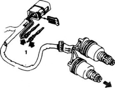
13.6v Cut the wire at the bushing and pull it out of the sleeve
7. Pull the new wire through the seal and sleeve (replace the seal).
8. Put on the sleeve, attach the terminal to the wire and crimp. Insert the terminal into the connector following the wiring diagram (photo).
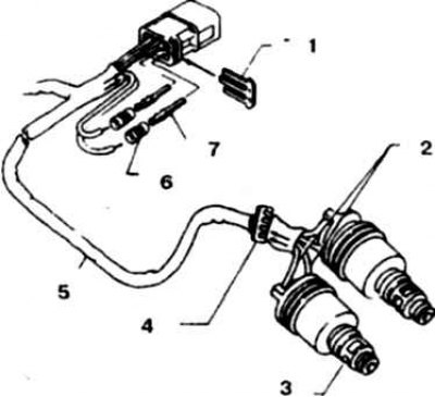
13.8a Connecting the injector wire
1. Retainer; 2. Wires; 3. New nozzle; 4. Through seal; 5. Sleeve; 6. Bushings; 7. Conclusions
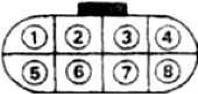
13.8b Diagram, color marking of wires and wiring diagram of the connector and wires of the injectors on V6 (VG30i) and Z24I (since 1987) engines with a preliminary injection system
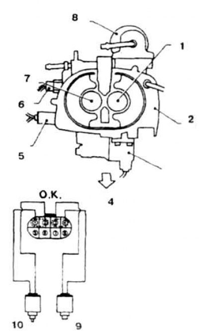
13.8v Location of injectors and valves on the valve body
1, 10. Nozzle A; 2. Damper body; 3. Thermoelement; 4. To the front of the engine; 5. Air conditioner idle speed control valve; 6. High idle speed valve; 7, 9 Nozzle B
9. Insert the lead into the connector.
| Purpose (to drive) | Connector pin number | Wire color |
| injector A (+) | 1 | G green |
| injector A (-) | 2 | W white |
| Nozzle B (+) | 3 | Blue |
| injector B (-) | 4 | R red |
| To the air conditioner idle speed control electromagnetic valve (+) | 5 | Into blue |
| To the air conditioner idle speed control solenoid valve (-) | 6 | Into blue |
| To the fast idle solenoid valve (+) | 7 | B/W blue white |
| To the fast idle solenoid valve (-) | 8 | B/W blue white |
Purpose (to the actuator (injector):
- + nozzles - green-white
- Injector A - to terminal 1
- Injector B - to terminal 3
- injectors - yellow-white
- Injector A - to terminal 2
- Injector B - to terminal 4
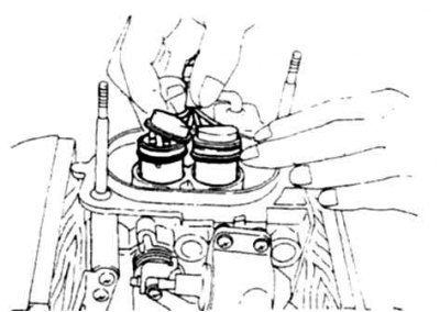
13.11 Installing injectors
12. Push the injectors in by hand, turn the housing over and make sure the injectors are installed correctly.
13. Lubricate the wire seal (photo).
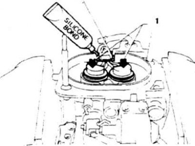
13.13 Lubrication of through-hole wire seal with silicone compound
1. Push in
14. Install the injector cover, tighten the screws, lubricate with a fixing compound and tighten in a crosswise order.
15. Lubricate the housing gasket with silicone compound (install the air filter only after the silicone sealant has set).
16. Install the damper body in reverse order.
17. Make sure there are no leaks, check the quality of the mixture at a car service center (to ensure that there is no air leakage through the upper injector seal).
Direct injection systems
18. Perform decompression, disconnect the battery from ground and drain the fluid.
19. Disconnect the wires from the spark plugs, remove the distributor cap and move the wires to the side.
20. Label and disconnect all wiring connectors, cables and hoses at the front of the intake manifold (photo).
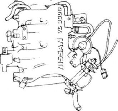
13.20 Intake manifold on V6 engines
21. On V6 engines, remove the bolts and intake manifold.
22. Disconnect the fuel pipes from the distributor with injectors.
23. Disconnect the injector connectors (photo).
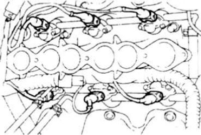
13.23 Injector connectors on a V6 engine
24. Remove the distributor with injectors.
25. Unscrew the bolts and remove the injectors (photo).
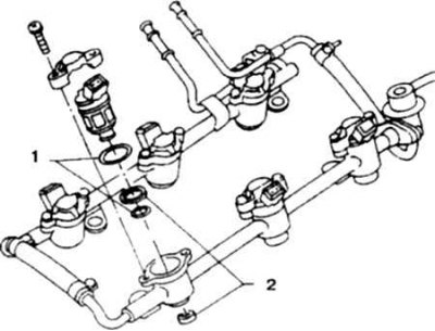
13.25 Nozzle mounting parts
1. Rings; 2. Insulating bushings
26. Before installation, moisten the new rings with gasoline and install the new injectors by pressing them into the distributor.
27. Install the distributor assembly with the injectors, tighten the bolts and tighten them.
28. Connect the connectors to the injectors.
29. Clean and install the manifold, replacing the gasket.
30. Tighten the manifold mounting bolts to the intake manifold. Tighten to the specified torque.
31. Attach the recirculation tube, hoses, wires and cables without disturbing their previous installation. Attach the wire clamps.
32. Install the pressure regulator. The remaining operations are performed in reverse order.