Direct fuel injection system
1. The processor unit processes information from the sensors and controls the operation of the ignition and fuel injection systems, maintaining the stoichiometric ratio of gasoline and air. The block also provides diagnostics of systems and includes control lamps. The unit has a built-in stabilized power supply for various sensors.
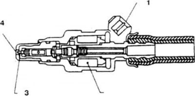
2. Crankshaft rotation sensor (photo) generates the main signal for the ECCS block. It consists of a rotor with a slit structure and a shaper assembled on an optical pair. There are 2 groups of slots on the rotor - spaced 1°apart (for registration of rotation) and paired slots located through 120° (to register the rotation of the crankshaft relative to TDC).
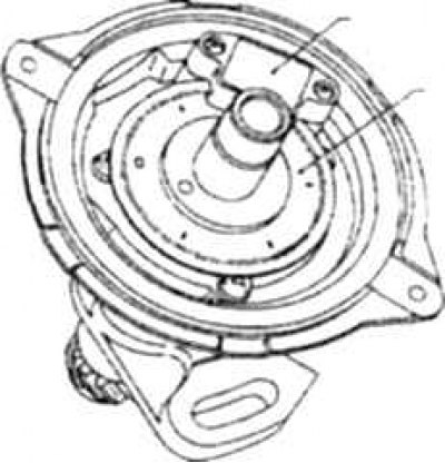
10.2a Crankshaft rotation sensor
1. Rotation angle sensor; 2. Rotor
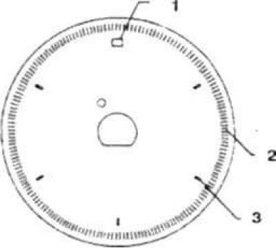
10.2b Slotted structure of the rotor
1. Reference slot for the 1st cylinder; 2. Slot for registration of rotation; 3. 120°angular displacement signal slot
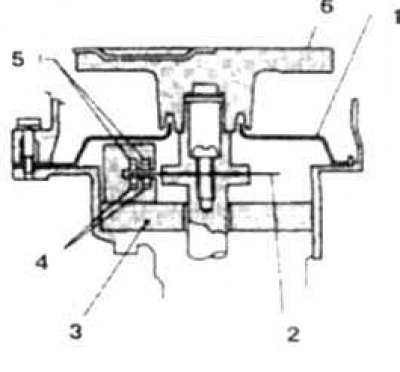
10.2v Crankshaft rotation sensor circuit
1. Lid; 2. Rotor; 3. Shaper; 4. Photodiode; 5. LED; 6. Slider
Flow rate sensor
3. Hot-wire type sensor, designed to measure the volume flow of air supplied to the cylinders (photo).
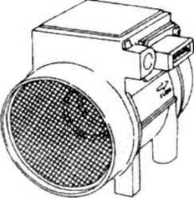
10.3 Air flow sensor
Engine temperature sensor
4. The sensor registers the temperature of the coolant and is connected to the processor unit (photo).
10.4 Engine temperature sensor 1. Sensor connector (on V6 engine) 2. Sensor (on the K24 engine)
Exhaust gas sensor
5. Screwed into the exhaust manifold, designed to monitor the oxygen content in the exhaust gases (photo).
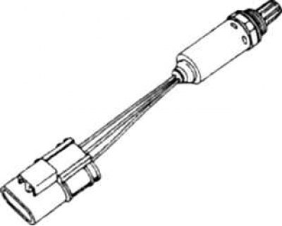
10.5 Exhaust gas sensor
Throttle switch
6. Designed to identify the idle mode. At idle, the sensor contacts are closed, when you press the throttle pedal, the contacts open (photo).
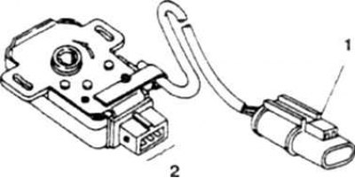
10.6 Throttle switch
1. Gate sensor connector; 2. Switch connector
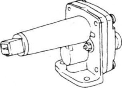
Vehicle speed sensor (VSS sensor)
7. Designed to generate a vehicle speed signal supplied to the processor unit, built into the speedometer. On a pointer speedometer, the sensor is a reed switch, on a digital sensor it is made in the form of an optical pair with a pulse shaper.
Knock sensor
8. Piezoelectric type knock sensor, designed to detect detonation in cylinders (photo).
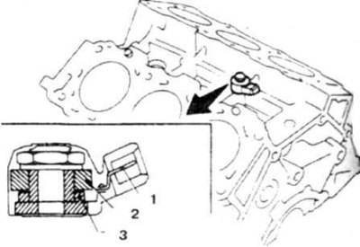
10.8 Knock sensor on the V6 engine
1. Conclusion; 2. Counterweight; 3. Piezo element
Nozzle
9. Solenoid valve designed to supply fuel to the cylinders. Contains coil and needle valve. Triggered by a pulse from the processor unit (photo).
10.9 Nozzle arrangement
1. Conclusion; 2. Winding; 3. Valve; 4. Nozzle
Power transistor block
10. Designed to amplify ignition signals from the processor unit, switch the primary circuit of the ignition coil and receive high voltage pulses (photo).
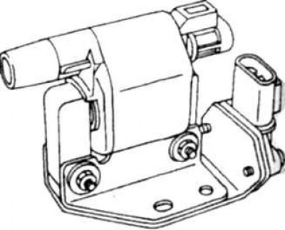
10.10 Ignition coil transistor unit
Ignition coil
11. Designed to receive high voltage pulses (photo).
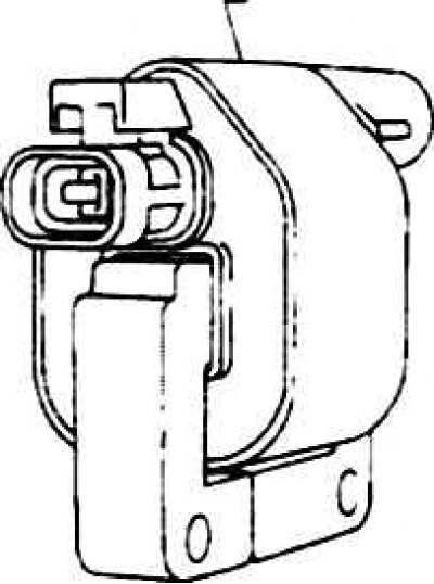
10.11 Ignition coil
Bypass valve (AAC valve)
12. Regulates the amount of air supplied directly to the cylinders at idle, bypassing the throttle. Controlled by the processor unit.
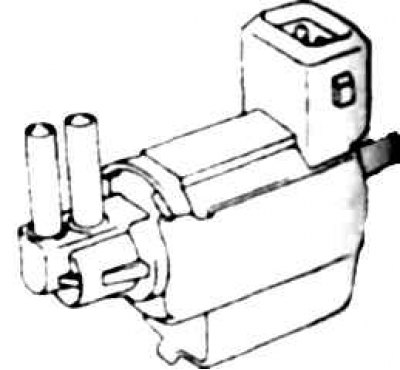
Idle speed stabilizer (IAA block)
13. Consists of bypass valve and adjusting screw. Designed to stabilize idling (photo).
10.13 Idle stabilizer
1. Bypass valve; 2. Screw
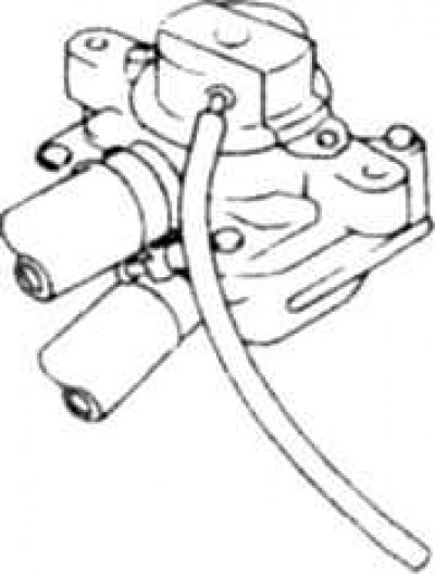
Pneumatic recirculation valve
14. Controls the amount of exhaust gases entering the intake manifold through a cone valve rigidly connected to a vacuum diaphragm (photo).
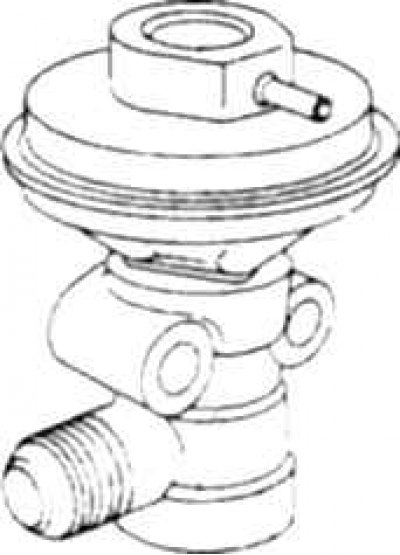
10.14 Pneumatic recirculation valve
Recirculation solenoid valve
15. Closes the vacuum channel of the recirculation pneumatic valve diaphragm in response to interrupt signals from the processor unit (photo). When the solenoid is off, the vacuum from the manifold is applied to the pneumatic valve. When the solenoid is turned on, the valve plunger closes the vacuum port.
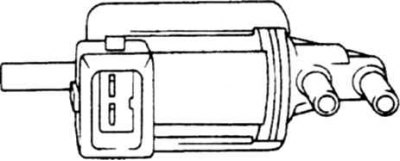
10.15 Recirculation solenoid valve
Fuel pump
16. Immersion type, tank mounted (photo).
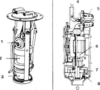
10.16 Fuel pump
1, 5. Damper; 2, 7. Pump; 3. Filter; 4. Exit; 6. Electric motor; 8. Pressure reducing valve; 9. Login
Air flow regulator
17. Provides switching of a cold engine to increased idle speed by opening the bypass channel (photo). Consists of a shutter with a thermoelectric drive.
10.17 Air flow regulator redirects flow to the manifold bypassing the throttle
Air ejection valve (AIV valve)
18. Provides air flow into the exhaust manifold due to ejection, which is necessary for afterburning the remains of incompletely burned fuel (photo). When the pressure in the manifold rises, the reed check valve is activated, preventing gases from entering the air filter.
10.18 Air induction valve
Electropneumatic valve controlling the AIV valve
19. Triggered by the processor unit and provides unlocking of the ejection valve in response to the appearance of a vacuum from the suction manifold (photo).
10.19 Electro-pneumatic valve of the exhaust gas post-oxidation system.
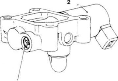
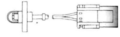
Power steering pressure sensor
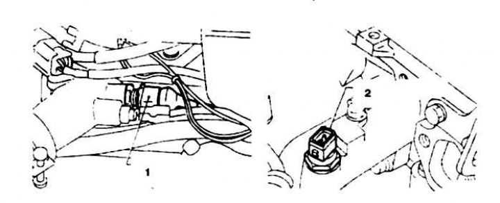
20. The sensor is screwed into the hydraulic booster high pressure line. The signal from the sensor is used to adjust the idle speed when the power steering is turned on (photo).
10.20 Power steering pressure sensor
1. Sensor connector; 2. Sensor; 3. Steering gear
Air temperature sensor
21. Designed to correct ignition timing at elevated manifold air temperatures to prevent detonation (photo).
10.21 Air temperature sensor
Injection system with preliminary preparation of a combustible mixture
22. The system includes one or two nozzles mounted on the throttle body. The injectors are controlled by the processor unit. Many units of this system are similar to those of the direct injection system (photo).
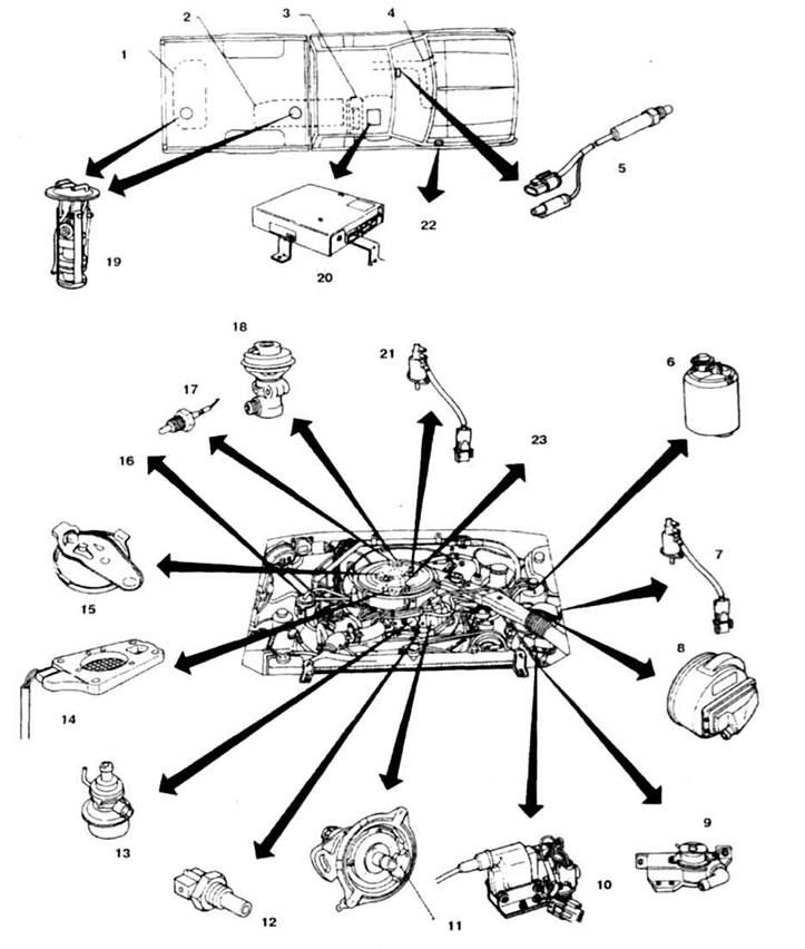
10.22а Arrangement of units injection system with preliminary preparation of a combustible mixture on a V6 engine
1. Buck (station wagon); 2. Buck (freight car); 3. Assistant's seat; 4. Exhaust pipe; 5. Exhaust gas sensor; 6. Tank with absorber
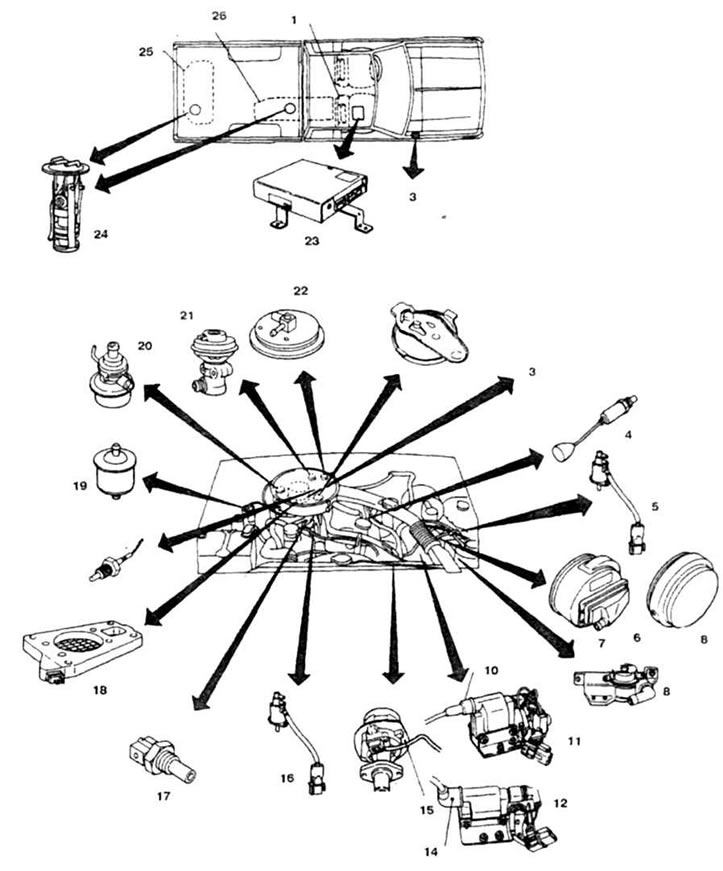
10.22b Arrangement of units injection system with preliminary preparation of a combustible mixture on a 4-cylinder engine
1. Assistant's seat; 2. Alarm relay; 3. Injection system parts: flow rate sensor, damper rotation sensor, idle switch
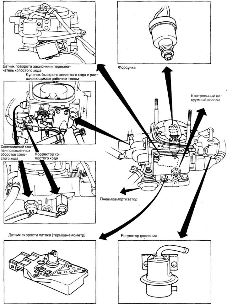
10.22v Throttle body parts (until 1989)