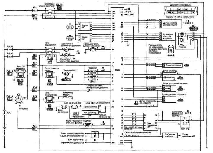
Wiring diagram
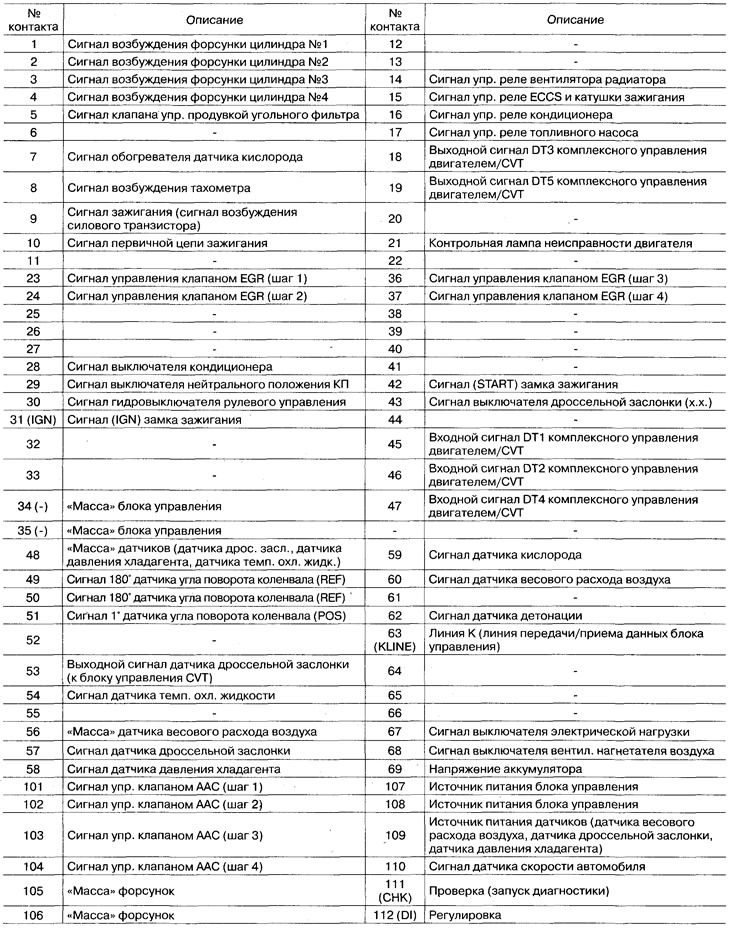
Pin assignment of the ECCS control unit connector
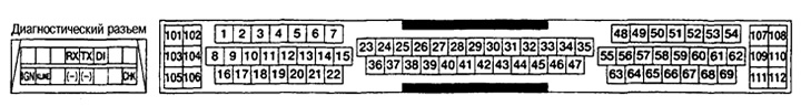
() The names of the signals are indicated on the contacts of the diagnostic connector (SR motors do not use RX and TX pins).
Standard input/output voltages of the ECCS control unit
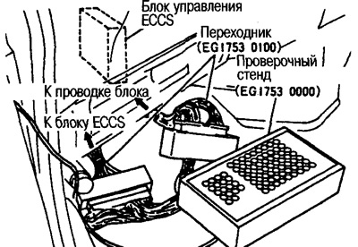
Measurements are carried out using an oscilloscope and a tester.
Below are the voltage values measured by the tester on the contacts of the ECCS control unit and the oscillogram.
Measurement data varies based on major factors (mode of operation, environmental conditions, service conditions, instruments used, measurement methods, etc.). The data given are standard values.
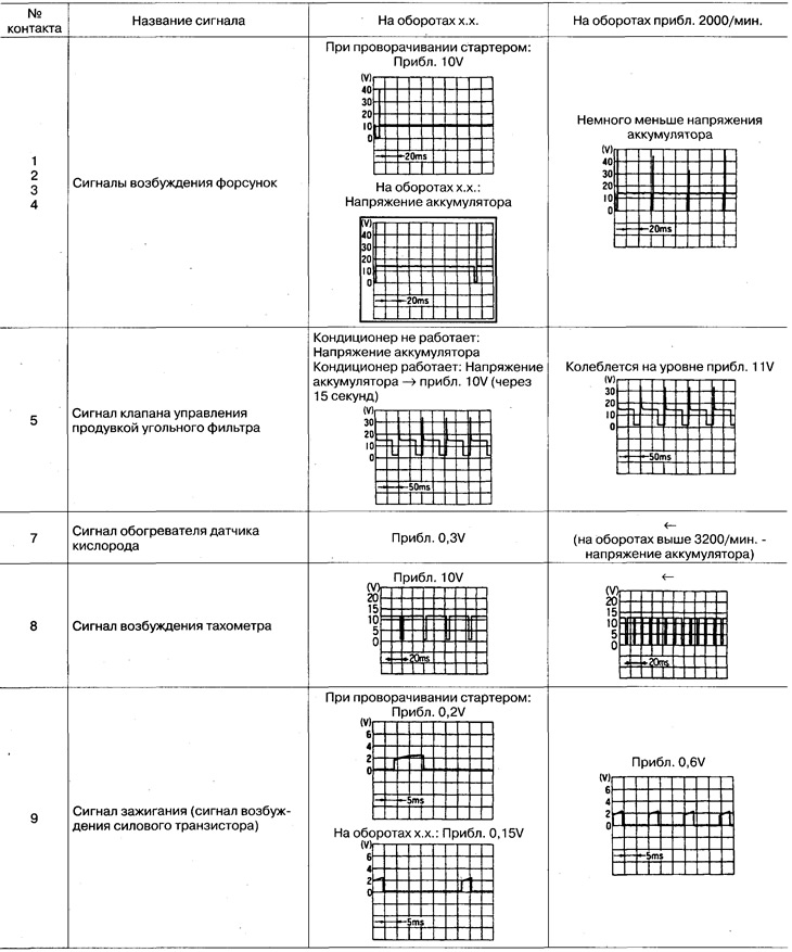
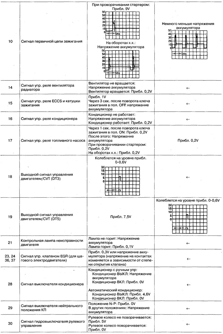
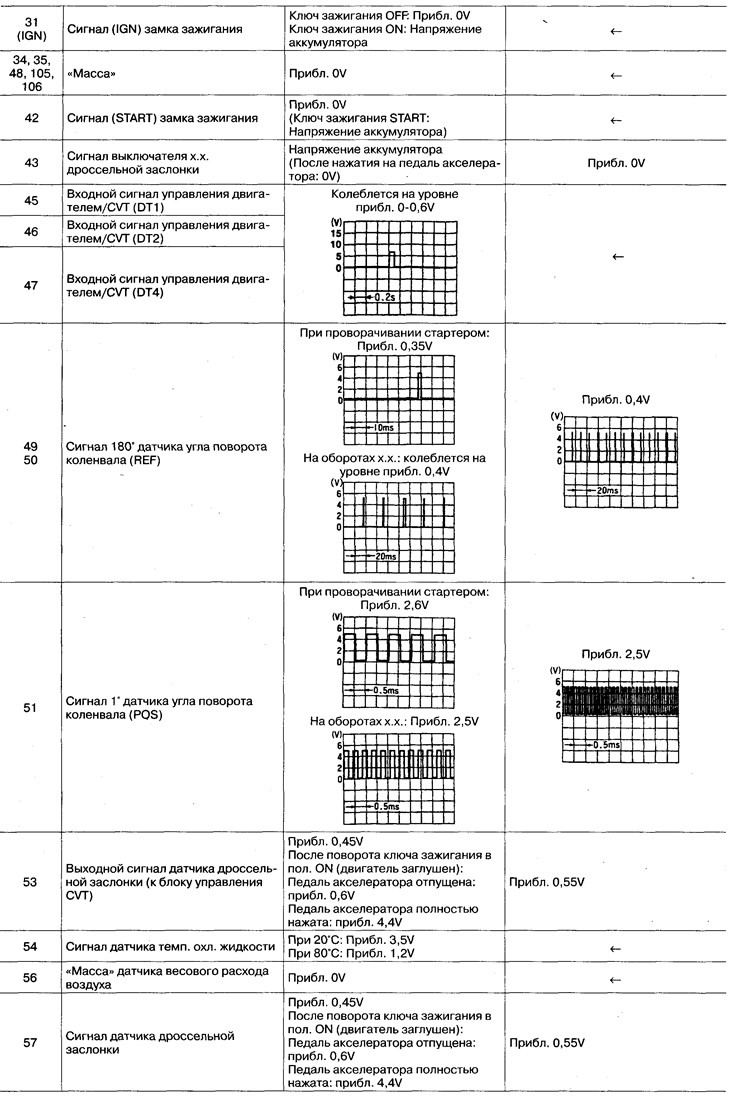
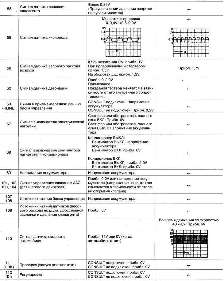
The voltages given are the values measured by the analog tester.