


Checking and adjusting high idle speed
1. Warm up the engine.
2. Make sure that the cam timing mark is opposite the center of the cam rod shaft. If not, adjust by turning screw S1. If adjustment is not possible, replace the heating element (photo).
3. Check the clearance G between the traction roller and the cam (photo). If necessary, adjust the clearance by turning the screw S2.
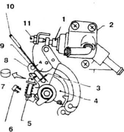
14.3 Adjusting the high idle speed on the throttle body
1. Thermoelement; 2. Heater body; 3. Gap G; 4. Throttle lever; 5. Adjusting screw S2; 6. Throttle valve adjusting screw; 7. Remove the cap; 8. Traction
Air conditioner idle speed control (FICD system) checking and adjustment
4. Warm up the engine.
5. Check the idle speed.
6. Turn on the air conditioner and check the idle speed.
7. If necessary, adjust by turning the screw (photo).
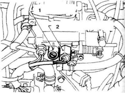
14.7 Adjusting the idle speed when the air conditioner is turned on
1. Adjusting screw; 2. Idle speed control valve
8. If the idle speed control valve fails, perform the following checks (photo).
- a). Disconnect the 8-pin connector.
- b). Turn on the ignition, set the air conditioner switch to the working position and check for voltage at the connector terminals (photo),
- c) Check the integrity of the valve winding.
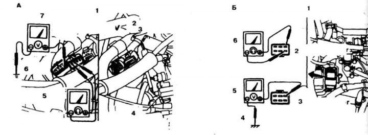
14.8 Checking the corrector valve on a V6 engine (A) and on a 4-cylinder engine (B)
A: 1, 4. Corrector valve; 2, 3. With the ignition and air conditioner on; 5. Checking the valve winding circuit; 6. Connection to ground; 7. Voltage verification; B: 1. Corrector valve
Air shock absorber check and adjustment
10. Warm up the engine. Check the idle speed, adjust if necessary.
11. Turn the damper by hand so that the air shock absorber rod touches the rod stroke adjustment screw and check the engine speed (photo).
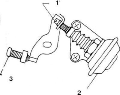
14.11 Adjusting the air shock absorber
1. Air shock absorber adjusting screw; 2. Air shock absorber; 3. Throttle valve adjusting screw
12. If necessary, adjust the speed by turning the adjusting screw.
Checking the high idle speed valve
13. Disconnect the 8-pin connector (photo) and check the valve winding circuit.
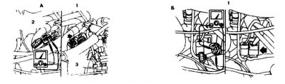
14.13 Checking the high idle speed valve on a V6 engine (A) and on a 4-cylinder engine (B)
A: 1, 3. Valve; 2. Checking the valve winding circuit; B: 1. Valve
14. If a break is detected, replace the valve. Tighten the new valve to the specified torque, replacing the gasket.
Direct injection system
High idle speed system check and adjustment (k24J engine)
15. Warm up the engine.
16. Stop the engine and remove the air filter.
17. Make sure that the alignment mark (Q) is aligned with the center of the roller (photo).
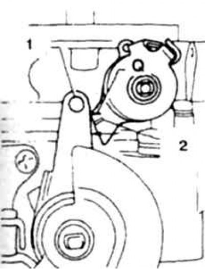
14.17 The Q mark must be located opposite the center of the roller
1. Roller
18. Adjust the cam by turning the screw until the top edge of the cam is aligned with the center of the roller (photo).
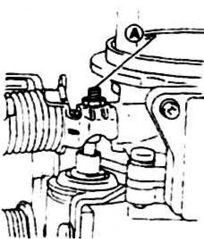
14.18 Cam adjusting screw (A) and lock nut
19. Check the clearance G between the roller and the cam (photo). If necessary, adjust the clearance by turning screw B.
Source is available on the resource [Nissanbook.ru]
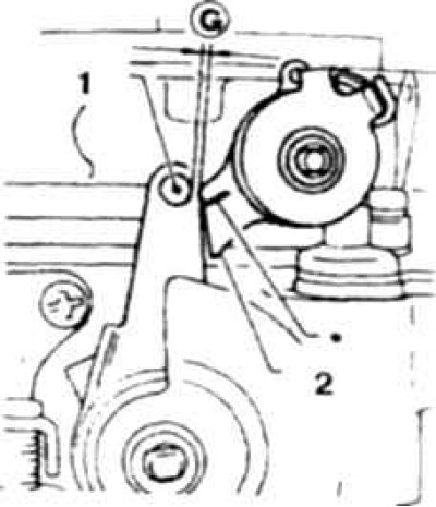
14.19a Clearance G between roller and cam
1. Roller; 2. Cam
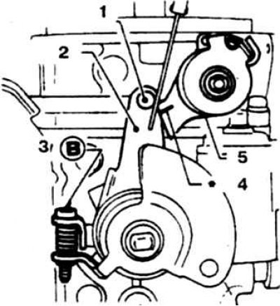
14.19b Throttle valve adjustment
1. Roller; 2. Traction; 3. Screw B; 4. This label is intended for a different purpose (not for adjustment); 5. Cam