2. Decompress the fuel system (see below).
3. Disconnect the battery from the mass, disconnect the fuel hose on the damper body.
4. Connect a pressure gauge between the hose and damper body (photo). On the K24 engine, connect the pressure gauge in accordance with the diagram (photo).
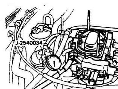
7.4a Installing the pressure gauge
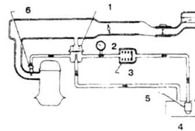
7.4b Scheme of switching on the control pressure gauge on the K24 engine
1. Pressure regulator; 2. Pressure gauge; 3. Fuel filter; 4. Tank; 5. Pump; 6. Nozzle
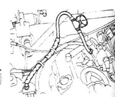
7.4c Installing a pressure gauge to check the pump on V6 engines with direct fuel injection. The pressure gauge is connected between the filter and the line on the engine side.
5. Connect the battery, start the engine and read the pressure gauge, which should be correct.
6. Stop the engine, remove the pressure gauge and connect the line.