


Table of contents: Replacing the pinion seal ↓ Removal ↓ Installation ↓ Disassembly ↓ Cleaning and checking the condition…↓ Assembly ↓
Note: The following special tools are required to perform the following procedures: Stillson wrench and pinion flange puller (to replace the pinion seal); the tools listed above, plus a bearing puller (for disassembly); press with support plates, sensitive low range torque wrench and dial gauge (for assembly).
Replacing the pinion seal
1. Jack up the front of the car and place it on supports placed under the frame side members.
2. Unscrew the drain plug and drain the oil from the front axle housing.
3. Mark the position of the front propeller shaft in relation to the pinion flange, then disconnect the propeller shaft from the flange and tie it to the side of the frame member with a piece of wire.
4. Mark the position of the pinion gear in relation to its flange (the main drive pinion with associated components is shown in the accompanying illustration).
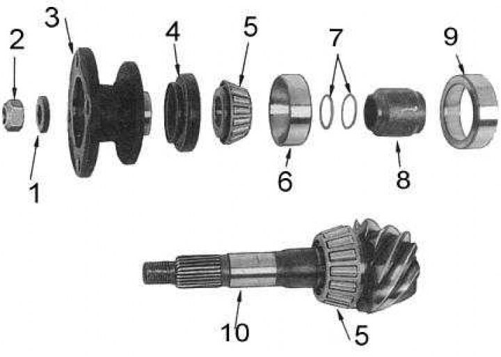
1 - washer; 2 - nut; 3 - flange; 4 - oil seal; 5 - bearing; 6 - clip; 7 - adjusting washers; 8 - spacer sleeve; 9 - cup; 10 - leading gear
5. Hold the flange still with a large Stillson wrench and loosen the pinion nut.
6. Using a puller, remove the flange from the gear.
7. Using a sliding hammer or a suitable lever, remove the oil seal from the crankcase.
8. Clean the seat for installing the oil seal in the crankcase and check its walls for burrs and scratches.
9. Fill the space between the lips of the new seal with universal lithium-based grease. Lubricate the outer edge of the seal with special grease and seat the latter perpendicularly into the main gear housing flush with its end.
10. Using a soft-faced hammer, install the drive gear into place, making sure that the marks made during dismantling are aligned.
11. Lubricate the nut with sealant, put on the washer and tighten the nut with a force of 196÷284 Nm.
12. Connect the cardan shaft to the flange (make sure that the marks applied during dismantling are aligned). Tighten the mounting bolts to 78÷88 Nm.
13. Fill the bridge housing with the required amount of oil of the required grade (see size and adjustment tables at the end of the Guide).
Removal
1. Remove the front wheel hubs and drive shafts.
2. Mark the position of the front propeller shaft in relation to the flange of the main gear pinion, then disconnect the shaft from the flange. Tie the shaft to the side of the frame member with a piece of wire.
3. Loosen the mounting nuts, remove the washers and release the brake pipe from the bracket. Disconnect the final drive assembly from the front axle housing. Remove the gasket from the assembly and discard it.
Note: The authors of this Manual recommend using an assistant to remove the final drive - the weight of the assembly is quite significant.
4. Check the axle housing for metal filings inside, the presence of which should be regarded as a sign of wear of the main gear. In this case, the assembly should be completely disassembled and defective or worn components should be replaced.
5. Clean the mating surfaces of the axle housings and the final drive assembly. Make sure that no debris gets inside the housings.
Installation
Installation is carried out in reverse order.
1. Install a new gasket on the axle housing (with the grey side facing the bridge).
2. Install the main gear assembly, screw on the fastening nuts and tighten them with a force of 54÷64 Nm. Connect the cardan shaft. Make sure that the marks made during dismantling are aligned. Tighten the fasteners with a force of 78÷88 Nm.
3. Install the drive shafts and front wheel hubs. Fill the axle housing with the required amount of oil of the required grade (see size and adjustment tables at the end of the Guide).
Disassembly
1. Remove the final drive assembly. Clamp it in a vice.
2. Before disassembling the assembly, perform the following checks:
- Using a dial gauge placed against the mating surface of the housing assembly, check the runout of the final drive driven gear. If the measurement exceeds 0.08 mm, check for foreign particles between the gear and the differential case. If none are found, replace the differential case.
- Using a dial gauge, check the radial clearance of the driven gear at four points. The nominal clearance value is 0.15÷0.20 mm. If the measurement result exceeds the specified value at any of the points being checked, (at an acceptable runout value) be sure to replace the driven and driving gears, or the differential box (depending on the circumstances).
3. Apply alignment marks to the side bearing caps and the adjacent surfaces of the final drive housing (see accompanying illustration).
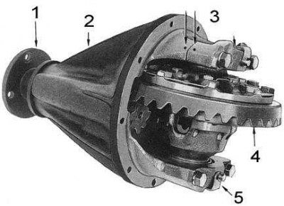
1 - leading flange; 2 - crankcase; 3 - landing marks; 4 - driven gear; 5 - locking tongue
4. Remove the retaining tabs from the side bearing caps, loosen the mounting bolts and remove the caps and adjusting nuts.
5. Using a wooden lever, support the driven gear with the differential assembly, pushing them out of the main gear housing. Try not to mix up the side bearing races - to be sure, apply identification marks to them.
6. Mark the position of the satellite axis relative to the pinion flange.
7. Secure the flange with a large Stillson wrench and loosen the drive pinion nut.
8. Using a puller, remove the flange from the drive gear, then remove the gear itself, spacer sleeve and adjusting washers from the crankcase (if necessary, use a soft-faced hammer).
9. Using a sliding hammer or suitable lever, remove the oil seal from the crankcase, then remove the pinion outer bearing cone.
10. Mark the mounting position of the driven gear on the differential case.
11. Bend the locking plates (if any are provided) mounting bolts of the driven gear of the main transmission.
12. Where necessary, bend the tongues of the locking plates of the driven gear mounting bolts.
13. Loosen the driven gear mounting bolts in a diagonal order, remove and discard the locking plates (if any are provided).
14. Using a soft-faced hammer, carefully tap the driven gear around the perimeter to separate it from the differential case.
15. On models with 2-satellite differential (the components are shown in the accompanying illustration) using a punch, knock out the pinion shaft locking pin from the side of the driven gear facing the differential case and remove the pinion shaft, pinions, differential side gears and thrust washers.
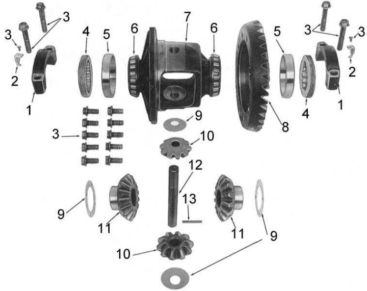
1 - lid; 2 - locking tongue; 3 - bolt; 4 - adjusting nut; 5 - clip; 6 - bearing; 7 - differential box; 8 - driven gear; 9 - thrust washer; 10 - satellite; 11 - differential side gear; 12 - satellite axis; 13 - pin
16. On models with 4-satellite differential (see accompanying illustration) mark the installation position of the differential box halves (lids and boxes themselves), then loosen the bolts that secure them to each other. Divide the differential box in half and remove the satellite axle assembly, satellites, side gears and thrust washers.
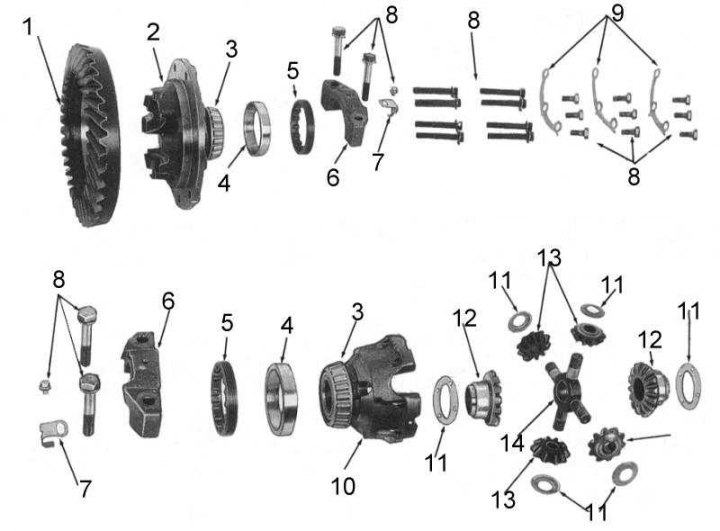
1 - driven gear; 2 - differential box cover; 3 - bearing; 4 - clip; 5 - adjusting nut; 6 - lid; 7 - locking tongue; 8 - bolts; 9 - lock washers; 10 - differential box; 11 - thrust washer; 12 - differential side gear; 13 - satellites; 14 - satellite axle assembly
Cleaning and checking the condition of components
1. Wash all components in solvent and dry them with compressed air.
2. Check the teeth of the driven and driving gears for signs of wear, chips and other damage.
3. Check the pinion gears, differential side gears, thrust washers and pinion shafts for signs of wear or damage.
4. Inspect the differential box for cracks and other damage.
5. Check the side bearings and their cups for signs of wear, discoloration, and other damage. If necessary, remove the bearing cones from the box using a puller.
6. Check the pinion bearings for signs of wear, discoloration, or other damage. Replace the bearings if necessary, as follows:
- Using a suitable puller, remove the inner bearing cone and spacer sleeve from the pinion gear (if such is installed).
- If necessary, fit a spacer sleeve onto the pinion gear. Make sure that the sleeve is installed with the beveled end facing the pinion gear. Using a press with support plates, install a new bearing cone. Remember that force should be applied only to the inner race of the bearing and until the spacer sleeve rests against the shoulders of the pinion gear.
- Using a brass drift, remove the bearing cups from the final drive housing.
- Carefully install the new cups into the crankcase until they rest firmly against the shoulders.
7. Check the seal contact surface of the pinion flange for scoring and signs of wear. Replace if necessary.
Assembly
Assembly is carried out in the reverse order of disassembly.
1. Lubricate the components of the required grade with a lubricating compound.
2. On models with a 2-satellite differential, assemble the box:
- Install the side gears, thrust washers, satellites and satellite shaft into the box. Do not install the locking pin at this stage.
- Using a blade-type feeler gauge, measure the gap between the side gear thrust washer and the differential box wall. If the measurement result is outside the range of 0.15÷0.20 mm, replace the thrust washers with new ones of the appropriate thickness.
- Align the satellite axle by aligning the locking holes and install the pin in place until it is fully seated in the differential box.
- Lubricate the satellites and side gears with the required grade of grease and check that they rotate freely.
3. On models with 4-satellite differential for gearbox assembly:
- Install the side gears, thrust washers, satellites and satellite axle assembly into the main half of the box.
- Press the flatness gauge (steel ruler edge) to the rear surface of the side gear thrust washer on the upper side of the differential and, having blocked the gears from rotating, measure the distance between the mating surface of the differential case and the edge of the flatness gauge using a vernier caliper. Record the measurement result (A).
- Press the flatness gauge against the mating surface of the differential case cover and use a vernier caliper to measure the distance between the contact surface of the side gear thrust washer and the edge of the gauge. Record the result (B).
- Calculate the side gear thrust washer clearance by subtracting dimension B from dimension A. If the calculation result is outside the range of 0.15÷0.20 mm, replace the thrust washers with new ones of the required thickness.
- Assemble the two halves of the differential box together (make sure that the landing marks applied during dismantling are aligned). Screw in the mounting bolts and tighten them to 64÷74 Nm.
- Lubricate the differential gears and thrust washers with the required grade of grease and check the freedom of rotation of the gears.
4. On models with a 2-satellite differential, lubricate the surfaces of the differential case that contact the driven gear of the final drive with a locking sealant.
5. Install the driven gear on the differential case, using a soft-faced hammer if necessary. Make sure that the mounting marks made during dismantling are aligned.
6. Lubricate the driven gear mounting bolts with a locking sealant, screw in the bolts, installing new locking plates under them (if any are provided).
7. Tighten the bolts with a force of 132÷152 Nm in a diagonal order, while lightly tapping their heads with a hammer. Bend the flags of the locking plates where necessary using a center punch.
8. Lubricate the outer edge of the new pinion seal with the required grade of grease. Fill the space between the seal lips with lithium-based general-purpose grease. Install the bearing and seal into the housing.
9. Lubricate the pinion rear bearing with the correct grade of grease, then install the pinion, spacer sleeve and adjusting washer into the housing. Holding the pinion still, tap the flange onto it with a soft-faced hammer.
10. Make sure that the threads on the drive gear and the mounting nut are not contaminated with grease or oil, lubricate the threads of the nut with sealant.
11. Install the washer, then screw on the nut and tighten it to 196÷284 Nm.
12. Turn the pinion gear several times in both directions. Put a torque wrench on the fastening nut and determine the preload of the pinion bearing. If the preload value is outside the range of 1.3÷1.6 Nm, replace the bearing adjusting washer with another one of the corresponding thickness.
13. Install the cups onto the side bearing cones and place the differential and pinion assembly into the final drive housing, making sure the bearing cups are positioned correctly. If old side bearings are used, make sure the cups are installed on the same sides as before disassembly.
14. Screw in the adjusting nuts of the side bearings, making sure that they are correctly seated in the threads in the main gear housing.
15. Align the seat marks on the side bearing caps and the main gear housing, install the bearing caps and tighten the bolts by hand. If the cap does not fit evenly when pressed by hand, the bearing adjusting nut is not correctly aligned with the cap.
16. Using a dial gauge, check the radial play of the final drive driven gear. If the measurement is greater than 0.02 mm, loosen the adjusting nut on the drive gear side and tighten the opposite one by the same number of turns. If the play is less than 0.15 mm, perform the procedure in the reverse direction.
Note: If the amount of axial play varies at different points on the driven gear, check whether foreign particles have entered between the gear and the differential case. If such particles cannot be found, replace the drive and driven gear or the differential case.
17. Turn the drive gear several times in both directions, then use a torque wrench on its mounting nut to check the overall differential preload. If the measurement result is outside the range of 1.8÷2.5 Nm, loosen or tighten both adjusting nuts accordingly. Having achieved the required differential preload, check the radial play of the driven gear again.
18. Tighten the side bearing cap mounting bolts to 93÷103 Nm.
19. Install the locking tabs and tighten the bolts securely. Press the plunger of the dial gauge against the supporting surface and check the runout of the driven gear of the main gear. If the measurement result exceeds 0.8 mm, remove the gear from the differential case and check for foreign particles between them.
20. Lubricate the surface of the teeth of the driven gear with Prussian blue or a mixture of red lead and oil, then, having fixed the flange of the driving gear, rotate the driven gear in both directions.
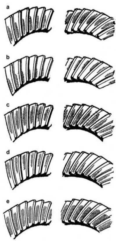
The location of the contact patch in the engagement of the main transmission gears (the left column is the forward side, the right column is the reverse side):
- a and b - incorrect contact, it is necessary to move the driving gear away from the driven one, reducing the thickness of the adjusting ring;
- c and d - incorrect contact, it is necessary to move the driving gear towards the driven one, increasing the thickness of the adjusting ring;
- e - correct location of the contact patch.
21. Inspect the surfaces of the driven gear teeth and compare the shape of the contact patch with the attached reference card (see accompanying illustration). If the required contact patch shape cannot be achieved, both gears (driven and driven) must be replaced.
22. Install the final drive assembly, drive shafts and front wheel hubs.