


Table of contents: General description ↓ Removal and installation the heater…↓ Removal and installation the heater…↓ Adjusting the heater control drive ↓
General description
The heater is controlled by four settings, allowing you to achieve a comfortable air temperature in the car.
The fresh air supply control lever allows you to set one of two heater operation modes - the outside air suction mode and the air recirculation mode. The recirculation mode involves the use of the heater fan and is usually switched on in very dusty areas or for the purpose of quickly warming up the car interior. Switching on the fresh air supply mode allows you to quickly ventilate the interior or remove condensation from the windows.
The flow direction switch lever allows you to direct heated air to the floor of the cabin, to the windshield or to the instrument panel nozzles. The lever has two fixed positions, the choice of which allows you to control the temperature of the air coming out of the nozzles located on the floor in relation to the temperature of the flow supplied through the nozzles of the instrument panel.
The temperature control lever allows you to change the position of the flaps that direct air either through the heater heat exchanger (in the HOT (Hot) mode) or bypassing it (in the COLD (Cold) mode). The maximum intensity of the heater is achieved only when the engine is warmed up to normal operating temperature.
The fan control lever allows you to turn the fan on/off and select the desired rotation speed.
Models equipped with air conditioning use a similar control panel with an additional button for turning the air conditioner on/off. The button is equipped with a control lamp that turns on simultaneously with the air conditioner.
The air conditioner can only be used when the engine is running, as the compressor is driven by the engine via a belt drive.
Turning on the air conditioner with the heater control lever set to the HOT position ensures the supply of dehumidified air to the passenger compartment, which, in particular, allows for the rapid removal of condensation from the car windows.
The maximum intensity of cooling of the air supplied to the passenger compartment is achieved by moving the temperature control lever to the minimum position (COLD). To avoid freezing of the evaporator in this mode, it is necessary to turn on the heater fan at maximum speed.
During the cold season, the air conditioner should be run for a short time (about ten minutes) at least once a month. Such regular inclusions will help to avoid drying out of the sealing gaskets and, as a consequence, failure of the air conditioning system.
Removal and installation the heater unit
Removal
1. Remove the instrument panel. The location of the heating and air conditioning components in the vehicle interior with the instrument panel removed is shown in the accompanying illustration.
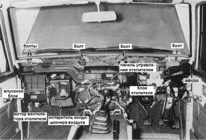
2. Empty the cooling system by draining the coolant into a clean container.
3. While working in the engine compartment, disconnect the hoses from the heater pipes.
4. Loosen the heater control panel assembly mounting bolts. Disconnect the panel bracket, then remove the control panel from the heater unit
5. Disconnect the control cables from the heater unit. Try to remember their installation position
6. Loosen the mounting bolts and remove the air vent from the passenger side of the vehicle.
7. Loosen the mounting bolts and remove the center ventilation duct.
8. After loosening the bolts, partially remove the ventilation duct from the heater unit, which runs from the driver's side of the car.
9. Release the wiring harness from the retainers at the front of the heater unit.
10. Remove the heater mounting bolts.
11. Remove the heater from under the engine compartment bulkhead. Try not to damage the heater tubes and water tap.
12. To remove the heat exchanger assembly with the tap, loosen the mounting clamp screws and release the clamps securing the tubes to the heater unit. Disconnect the water tap rod, remembering its position. Move the heat exchanger to the side, separating it from the heater unit.
Installation
Installation is carried out in reverse order.
1. Before installing the heater unit on the vehicle, adjust the water tap drive rod (the accompanying illustration shows the rear view of the heater. The data for adjusting the tap is given in the insert):
- Disconnect the control rod from the air lever;
- Pull the control rod back until the gap between the control lever and the drive lever is 2 mm;
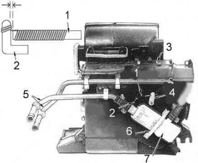
1 - control rod; 2 - traction; 3 - heater assembly; 4 - air temperature control lever; 5 - tubes; 6 - mounting clamp; 7 - heater heat exchanger
- Turn the air control lever fully clockwise and connect the control rod to the lever;
- Make sure that the heater tap is functioning properly by blowing into the heater tubes.
Note: Access to the tap is not possible without first removing the heater from the vehicle.
2. Try not to damage the heater tubes when installing the unit into its seat.
3. Check the correct installation of the heater tube bushing in the engine compartment bulkhead.
4. Before installing the instrument panel, check the heater control for proper operation. Adjust the drive if necessary.
5. With the engine running, turn on the heater, make sure it is functioning properly and check for leaks.
Removal and installation the heater control panel
Removal
1. Disconnect the negative cable from the battery.
2. Remove the central part of the instrument panel. The view of the heater control panel with the central part of the instrument panel removed is shown in the accompanying illustration.
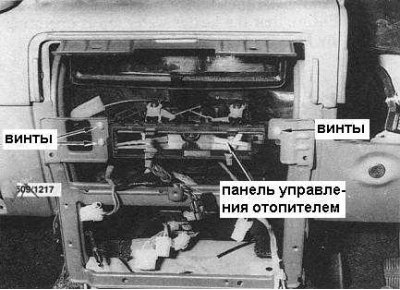
3. Remove the handles from the control levers by pulling them off the stems. Remove the heater control panel trim.
4. Loosen the mounting screws and pull the heater control panel assembly out far enough to allow the electrical connectors to be disconnected from the rear of the heater control panel.
5. Loosen the mounting screws and remove the glove box from the vehicle.
6. Release the temperature control cable retaining clamp on the heater unit and disconnect the cable from the actuator lever.
Note: If the heater control was working properly before removal, mark the position of each cable sheath relative to the heater unit with quick-drying paint or other suitable method. The cables should be connected in their original positions during reassembly.
7. Release the air control cable retainers at the bottom of the instrument panel and at the air intake block. Disconnect the cable from its actuator lever.
8. Working from the right side underneath the instrument panel, release the air flow control cable retainer and disconnect the cable from the actuator lever.
9. Loosen the mounting screws and remove the heater control assembly from the heater unit.
Installation
Installation is carried out in reverse order.
If marking was not done during dismantling, adjust the heater control drive cables.
Adjusting the heater control drive
Air flow control rods and cable
1. Disconnect the air flow control cable from the actuator lever.
2. Release the upper and lower flap levers and the defroster flap lever from the retaining clips. The drive components are shown in the accompanying illustration, which shows a view of the heater unit from the right.
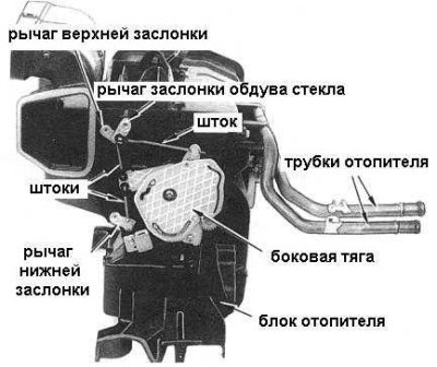
3. Push the side link counterclockwise until it stops.
4. Turn the upper and lower damper levers clockwise until they stop and install the lower rod first and then the upper rod.
5. Push the side rod clockwise until it stops. Turn the glass defroster lever counterclockwise until it stops and install the defroster rod.
6. Push the side link clockwise until it stops, set the air flow control lever to the face ventilation position, then connect the air flow control cable to the side link.
7. With the heater fan running at maximum speed, move the air flow control lever through all positions to ensure that it is functioning properly.
Temperature control rod and cable
Note: If the control rod requires adjustment, the heater must be removed from the vehicle.
1. Loosen the mounting screws and remove the glove box from the vehicle.
2. Set the temperature control lever to the maximum heat position.
3. Push the temperature control lever fully clockwise while slightly pulling the control cable housing to take up any slack and secure the cable in the retainer clamp.
4. Warm up the engine to normal operating temperature and check the temperature control lever for proper operation.
5. Replace the glove box.
Air supply control cable
1. Loosen the mounting screws and remove the glove box from the vehicle.
2. Working in the footwell on the passenger side of the vehicle, release the air control cable from the retainer on the air intake manifold.
3. Set the air supply control lever to the recirculation mode position.
4. Push the feed control lever forward towards the vehicle until it stops and secure the control cable in the retainer clamp.
5. Check the proper functioning of the air supply control.
6. Replace the storage compartment.