


A cylinder bank is a separate group of cylinders that share a common control sensor. The first row of cylinders always contains cylinder #1, and the second row of cylinders is the row of cylinders opposite the first.
The vehicle also has two rear heated oxygen sensors, designated No. 2, located on each bank of cylinders.
The sensor number is assigned to take into account the location of the sensor in relation to the air flow entering the engine. Starting from the intake duct towards the exhaust pipe, the numbering is in order: 1, 2, etc.
Oxygen sensor locations
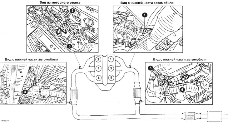
1 - heated oxygen sensor No. 1 (first row of cylinders); 2 — heated oxygen sensor wiring harness plug No. 1 (second row of cylinders); 3 - heated oxygen sensor No. 1 (second row of cylinders); 4 - heated oxygen sensor No. 2 (second row of cylinders); 5 - heated oxygen sensor No. 2 (first row of cylinders); 6 — heated oxygen sensor #2 wiring harness plug (first row of cylinders).
The oxygen sensor compares the amount of oxygen in the exhaust gases with its content in the surrounding air and produces a measured signal.
Under normal conditions, the optimal air/fuel ratio is 14.7:1. This ratio is maintained by measuring the oxygen content in the exhaust gases using an oxygen sensor. The oxygen sensor's operating temperature range is 285–832°C. The sensor is electrically heated to quickly reach operating temperature. When the ignition is on, current is supplied to a resistor whose resistance increases with increasing temperature. As a result, the sensor quickly reaches operating temperature even at low exhaust gas temperatures.
Exhaust gases enter the outer surface of the sensor through holes in the protective sleeve. The surrounding air enters the inner surface of the sensor through the channels. The sensor is a zirconium oxide tube coated with platinum.
The signal magnitude is proportional to the amount of oxygen in the exhaust gases. This depends on the air/fuel ratio. A lambda value of 1 indicates a theoretically ideal ratio. A richer mixture results in a higher signal voltage, a leaner mixture results in a lower voltage.
The signal sent by the oxygen sensor to the control unit varies between 0.1 and 1.0 V. The difference between high and low voltage occurs when the lambda value is 1. The control unit uses this information to regulate the amount of fuel injected.
Contamination can directly affect engine performance and the life of the oxygen sensor. There are three main types of contaminants: carbon, lead, and silicon. Carbon deposits due to rich mixture operation cause incorrect readings and aggravate fault symptoms. Diagnose the injection system for correct adjustments. When the system is being repaired, run the engine at high speed without load to remove carbon deposits. Do not use leaded gasoline as this will cause lead contamination of the oxygen sensor. Also avoid using older types of silicone sealants, which contain volatile compounds that will leach into the end of the sensor. Always check that the sealant you use is approved for modern exhaust systems. Before the oxygen sensor begins to function properly, it must reach a minimum operating temperature of 15°C. The warm-up period to this temperature is often referred to as the open-loop mode. In this mode, the ECM detects low coolant temperature (cold engine starting) and wide open throttle (engine warm-up). While the engine is warming up to operating temperature, the ECM ignores the oxygen sensor signals. During this time, exhaust emissions control will not be complete. When the engine is warmed up, the system switches to the feedback mode (using the oxygen sensor signal). The oxygen sensor has an electric heating element to quickly warm up the sensor to operating temperature. Use caution when testing the oxygen sensor circuit. Clearly define the function of each wire, otherwise you may confuse the data and draw erroneous conclusions.
The oxygen sensor monitors the oxygen content in the exhaust gas stream.
The oxygen content in the exhaust gases is displayed by the sensor as a voltage and varies from 0.05 V (high oxygen content, lean mixture) up to 2.2 V (low oxygen, rich mixture). The control unit continuously monitors this changing voltage to determine the ratio of oxygen to fuel in the air-fuel mixture.
Proper operation of the oxygen sensor depends on 4 conditions:
- Electrical - Low voltages generated by the sensor depend on the quality and cleanliness of the connections, which should be checked if sensor malfunction occurs or is suspected.
- Outside air supply - the sensor is designed for air circulation in the internal part of the sensor. When removing and installing or replacing the sensor, make sure the air passages are not clogged.
- Correct operating temperature - the control unit will not respond to the sensor signal until it reaches a temperature of approximately 285°C. The oxygen sensor does not output voltage when its temperature is below operating temperature. When the engine warms up, the control unit operates in emergency mode. This must be taken into account when evaluating the performance of the sensor.
- Unleaded Fuel - The use of unleaded gasoline is necessary for the sensor to function properly. Make sure the petrol is unleaded.
In addition to observing the above conditions, special precautions must be taken when working with the sensor:
- The oxygen sensor has permanently attached wires and a connector that cannot be removed from the sensor. Their damage or removal can significantly affect the operation of the sensor.
- Keep grease, dirt and other contaminants away from the connector and open end of the sensor.
- Do not use cleaning agents or solvents to clean the oxygen sensor.
- Do not drop the sensor and handle it with care.
- The silicone case must be installed in the correct position to avoid melting and ensure proper operation of the sensor.
Removal
Disconnect the negative cable from the battery.
Raise the vehicle and support it securely on stands.
Disconnect the oxygen sensor connector. The sensor is located near the catalytic converter.
Remove the oxygen sensor using a suitable wrench.
Installation
Installation is carried out in the reverse order of removal. Before installation, lubricate the threads with a special paste. Tighten to 55 Nm.
Examination
Oxygen sensor #1 (front)
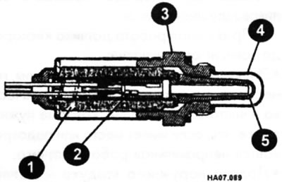
1 - insulator; 2 — heater pad, 3 — holder; 4 - grille; 5 - zirconium tube.
- Check the resistance between contacts (a) and (c).
Required resistance value: 3.3 + 1.00 Ohm at 25°C.
- Check the conductivity between contacts (b) and (c), (a) and (b).
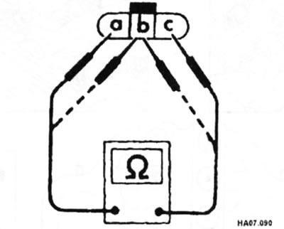
Required value: there should be no conductivity.
Oxygen sensor #2 (rear)
The rear oxygen sensor does not control engine operation.
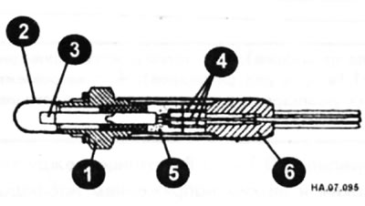
1 - holder; 2 - grille; 3 - sensitive element; 4 - contacts; 5 - insulator; 6 - rubber core.
- Measure the resistance between contacts (a) and (c) (see figure NA.07.090).
The required resistance value is 6.7+1.5 Ohm at 25°C.
- Measure the resistance between contacts (b) and (c), (a) and (b), as shown in Figure HA.07.090 above.
Required conditions: there must be conductivity.
- If the measurement results do not match the required values, replace the rear oxygen sensor.