Table of contents: Removal and installation ↓ Examination ↓
This sensor is a negative temperature coefficient of resistance type and is a thermistor in which the resistance decreases with increasing temperature.
Information about the coolant temperature is of great importance for calculating the injection duration and controlling the radiator fan. For example, if the engine is started from a cold state, the amount of fuel injected must be significantly greater.
If the control unit receives a signal that the coolant temperature is above 150°C or below -40°C, this signal is interpreted as false and a fault code is generated. In this case, the control unit is guided by a value of 0°C when the engine is started and a value of 20°C when the engine is running. The radiator fan runs at low speed and the adaptive injection duration control is not active.
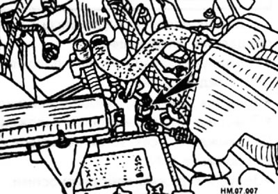
Knock control operates at idle speed. The location of the sensor is indicated by the arrow in the figure below.
To determine the fault code:
- After turning the ignition key to the ON position, wait 5 seconds.
- After turning the ignition key to the OFF position, wait 3 seconds, then turn it to the ON position.
- Turn on self-diagnosis mode.
Removal and installation
- Turn the ignition switch to the OFF position.
- Drain the coolant from the system.
- Disconnect the temperature sensor plug and remove the sensor.
- Installation is carried out in the reverse order of removal.
The text was copied from the portal [NissanBook.ru]
Examination
Checking the signal
- With the ECM connected, connect a voltmeter between terminal 73 of the ECM connector and ground.
- Turn the ignition switch to the ON position.
♦ At 20°C the voltage should be 3.5 V.
♦ At 50°C the voltage should be 2.2 V.
♦ At 90°C the voltage should be 1.0 V.
Note: At 50°C the control unit changes the signal level for better resolution.
- If the sensor signal voltage is 0 V (the voltage supply circuit is open or shorted to ground), perform the following tests.
- Check that the signal contact on the sensor is not shorted to ground.
- Check the signal wires between the sensor and the electronic control unit.
- If the sensor wires are normal but there is no voltage output from the ECU, check all voltage supply and ground connections at the ECU. If these connections are normal, then the electronic control unit is suspect.
Checking with an ohmmeter
- The resistance can be checked at different temperatures and then compared with the data in the resistance temperature dependence table.
- To avoid disconnecting the ECM to perform these measurements, you can disconnect the coolant temperature sensor connector itself and connect an ohmmeter to its two contacts.
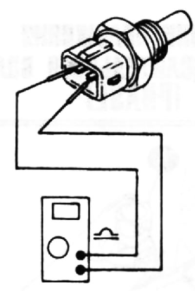
- If the sensor resistance differs from that given in the table at different temperatures, replace the sensor.
Required measurement results
| Temperature | Resistance |
| 20°C | 2.1-2.9 Ohm |
| 80°C | 0.27-0.38 Ohm |
- When the resistance is within the specified values for a cold engine (20°C), the coolant temperature should be within +5°C of the specified value.
- Allowance may be made for temperatures obtained from measurements outside the sensor or coolant passage. This happens because the true coolant temperature may be higher than the sensor surface temperature.
Checking the sensor outside the vehicle
- Remove the sensor from the vehicle.
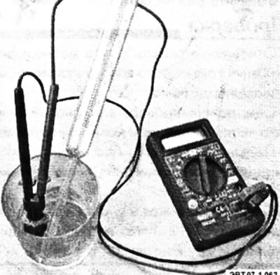
- Place the sensor in a suitable container of water and measure the water temperature.
- Measure the resistance of the sensor and check it against the temperature table.
- Heat the water, periodically measuring the water temperature and the sensor resistance and comparing them with the data in the table.