Warning! The car models covered in this manual are equipped with an additional security system (SRS). Before doing any work near the airbag unit, steering column or instrument panel, turn off the SRS to avoid injury if it is accidentally deployed (see chapter Onboard electrical equipment). SRS circuit wiring is easily identified by the yellow color of the insulation. To avoid damage to the SRS system, make sure that the steering shaft does not turn after removing the steering wheel. Block the column with the ignition key with the front wheels straight ahead.
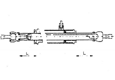
Steering rack and pinion design
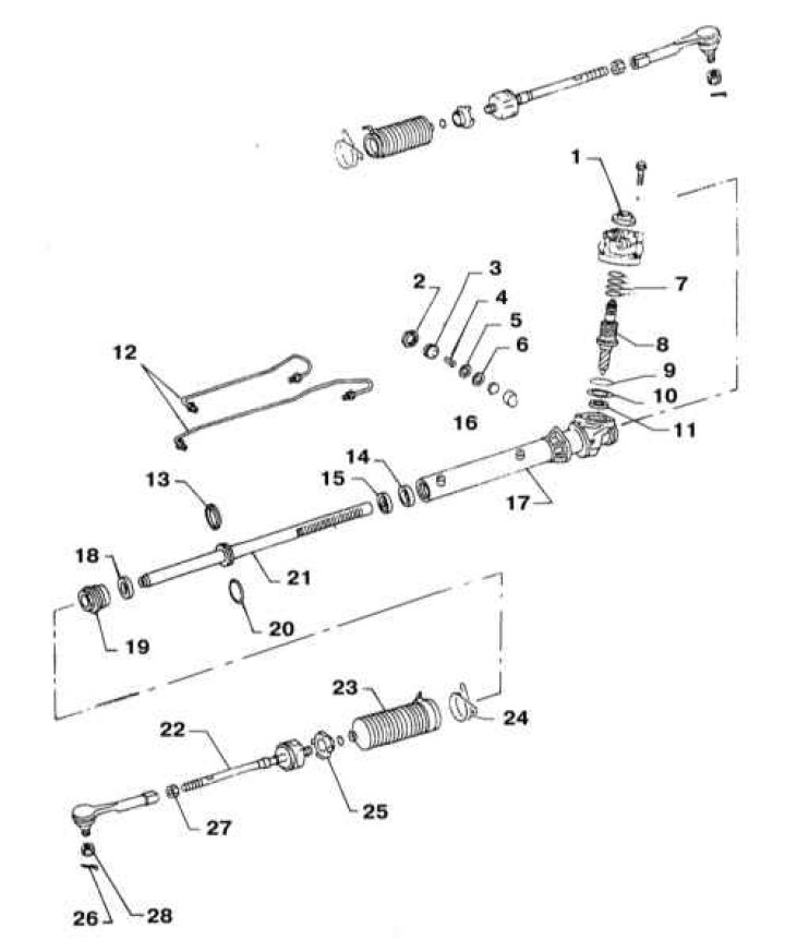
1 - Back cover; 2 - Lock nut; 3 - Adjusting screw; 4 - Spring; 5 - Spring plate; 6 - Washer; 7 - O-rings gear; 8 - Input gear of the steering mechanism; 9 - O-ring; 10 - Sealing gasket; 11 - Gear seal; 12 - Hydraulic lines (20 ÷ 26 Nm); 13 - O-ring; 14 - Central sleeve; 15 - Sealing cuff; 16 - Retainer; 17 - Carter rack transmission; 18 - Sealing cuff; 19 - End cap (59÷74 Nm); 20 - O-ring; 21 - Rake; 22 - Tie rod; 23 - Protective cover; 24 - Wire bandage; 25 - Lock washer; 26 - Cotter pin; 27 - Tie rod end locknut (78÷98 Nm); 28 - Tie rod end ball stud castellated nut (29÷39 Nm)
Removing
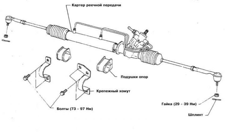
1. Details of the installation of the steering mechanism are shown in the illustration.
2. Park the vehicle with the front wheels turned straight ahead. Disconnect the negative cable from the battery. On models equipped with airbags, also disconnect the positive wire and wait at least 10 minutes before proceeding with the procedure.
3. Remove the air cleaner with intake duct (see chapter Power and exhaust systems). Remove the charcoal adsorber with its support bracket (see chapter Engine management systems).
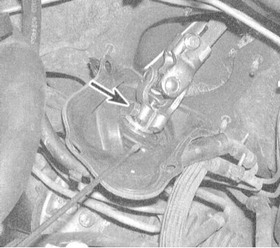
4. Give fixing nuts and remove from a bulkhead of an impellent compartment a protective cover of a universal joint. Mark the position of the universal joint relative to the input shaft of the rack and pinion, then remove the pinch bolt securing the lower intermediate shaft.
Attention! Do not turn the steering wheel with the rack and pinion removed on models equipped with airbags. If necessary, remove the steering wheel and center the spring contact (see Section Removal and installation of a steering wheel). To ensure that the steering wheel is stationary, use the seat belt.
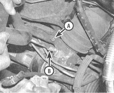
5. Insert a drain pan under the rack and pinion housing. Disconnect the pressure and return hydraulic lines from the steering gear housing. Seal open ends of lines immediately to prevent dirt from entering the system and to minimize hydraulic fluid loss.
6. Loosen the wheel nuts, jack up the front of the vehicle and place it on jack stands. Set the parking brake and remove the wheels. Remove the crankcase protection if the vehicle is equipped accordingly.
7. Release the tie rod ends from the steering knuckle arms (see Section Removal and installation of tips of steering draughts).
8. Remove the anti-roll bar (see Section Removal and installation of the front anti-roll bar).
9. Remove the central cross beam passing under the power unit (see chapter Engine).
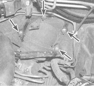
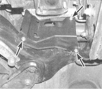
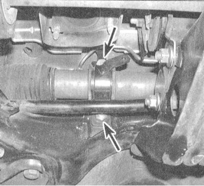
10. Give nuts of bolts of fastening of the steering mechanism. Separate the intermediate steering column shaft from the rack and pinion input shaft. Remove the steering gear assembly from under the vehicle.
 |  |
11. Check the condition of the pinion assembly bearing bushings. If there are signs of rubber destruction, replace the bushings.
Disassembly
1. The design of the rack-and-pinion transmission is shown in the illustration.
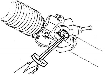
2. Before disassembling the rack and pinion, measure the tightening torque of the gear and record the result of the measurement as a recommended value. Disconnect the hydraulic line and drain the crankcase before measuring. Do not clamp an aluminum alloy crankcase in a vise.
3. Remove the gear, - try not to damage the o-rings.
4. Release the bandage and remove the protective cover.
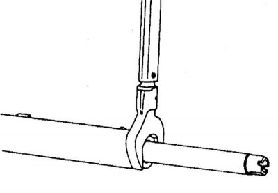
5. Disconnect the tie rod from the rack.
6. Release the latch and remove the drive gear assembly.
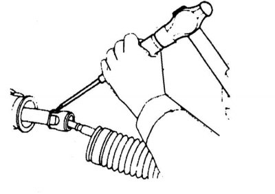
7. Drill out the mount on the end of the steering gear housing (use a 2 mm drill).
8. Remove the rack and pinion housing end cover.
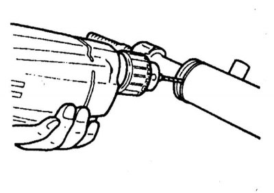
9. Remove the steering rack and remove the sealing ring from it - use a hair dryer, warming up the ring to a temperature of about 40°C.
10. Remove the central bushing and the steering rack seal, - try not to damage the inner surface of the gear housing.
Assembly
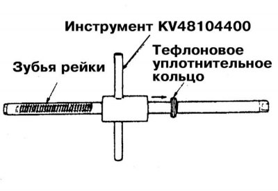
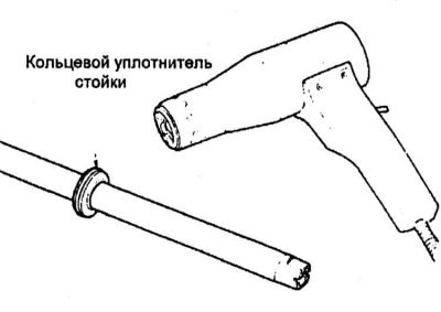
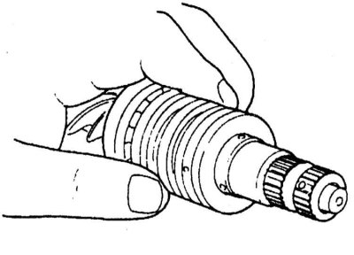
1. Before installing on the rail, heat the new Teflon O-ring with a hair dryer to a temperature of 40°C. Use a special tool to fit the ring.
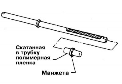
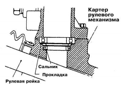
2. Install the rail seal. To prevent the risk of damage to the cuff on the teeth of the rack, thread a polymer film twisted into a tube inside it.
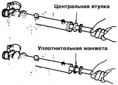
3. After installing the cuff, remove the polymer film from under it. Make sure the cuff fits correctly. Fit the center sleeve and cuff.
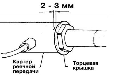
4. Tighten the end cap to the required torque and secure it with the lock nut.
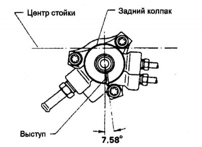
5. Bring rack and pinion to neutral position.
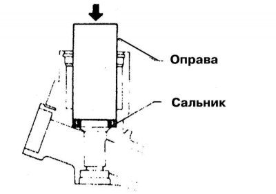
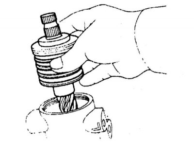
6. Lubricate the lip of the oil seal of the pinion assembly with multipurpose grease, then press in the oil seal using a suitable drift. Make sure that the protrusion of the gland is on the front side.
7. Install the gear bearing.
8. Remember to replace the gaskets with new ones with the same part number.
9. Install new O-rings on the gear. Before planting, heat the ring with a hair dryer to a temperature of 40°C. Make sure that the ring fits correctly in the valve groove.
10. Lubricate the ball joint and seal boss with multipurpose grease before installing the gear.
11. Fit the gear assembly into the steering box. Be careful not to damage the seal.

12. Lubricate the rear oil seal with multipurpose grease before installing the rear casing.
13. Install the back cover in accordance with the instructions in the illustration, - try not to damage the worm ring and the gland.
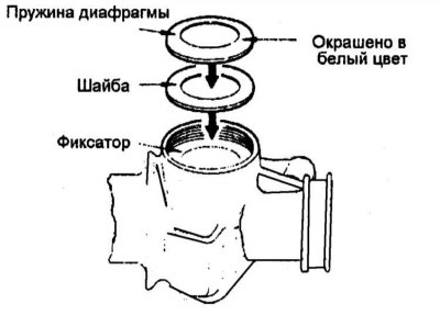
14. Acting in a strictly defined order), install the spring washer, diaphragm spring and retainer.
15. Make sure the diaphragm spring is installed with the white-painted convex side facing out.
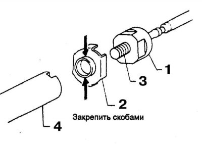
16. Install spring retainer and adjusting screw. Install a new lock washer. Attach lock washer (2) from the inside of the seat of the rod (1). For locking to internal thread (1) use sealant. Screw the socket onto the rail (4), tighten it to the required torque.
17. Bend the tabs of the lock washer.
18. Connect steering drafts and establish protective covers.
Installation
Note. Before installing, make sure that the rack and pinion is set to the middle position corresponding to the straight position of the front wheels of the car.
1. Move the steering gear assembly to its regular place and connect the steering shaft cardan joint to it (check the correct alignment of the landing marks).
2. Establish fixing collars, screw in bolts and tighten them with the demanded effort. Install the shield to the right mechanism support assembly.
3. Install the center cross member (see chapter Engine).
4. Install the anti-roll bar (see Section Removal and installation of the front anti-roll bar).
5. Connect the tie rod ends to the steering knuckle arms (see Section Removal and installation of tips of steering draughts).
6. Install the crankcase protection components.
7. Install the wheels, lower the vehicle to the ground and tighten the wheel nuts to the required torque (see chapter Settings and ongoing maintenance).
8. Screw in the cardan joint coupling bolt and tighten it with the required force. Install the hinge cover.
9. Connect the pressure and return hydraulic lines to the rack and pinion case. Top up the steering pump reservoir with the correct amount of hydraulic fluid of the correct grade (see chapter Settings and ongoing maintenance).
10. Replace the charcoal canister and air cleaner assembly with intake duct.
11. "Upgrade" steering system (see Section Removing air from the hydraulic path of the power steering system).