When using a new cylinder block and crankshaft
1. Determine the size group of the main bearing bed in the cylinder block by the mark located on the rear left side of the block (L) and use this value to select row «Selection tables for main bearing shells».
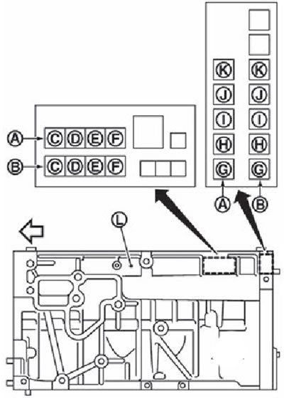
A. Correction stamp.
B. Standard stamp.
C. Dimensional group of the opening of the first cylinder.
D. Dimensional group of the hole of the second cylinder.
E. Dimensional group of the hole of the third cylinder.
F. Fourth cylinder bore size group.
G. Dimensional group of the bed of the main bearing of the support No. 1.
N. Dimensional group of the bed of the main bearing of the support No. 2.
I. Dimensional group of the bed of the main bearing of the support No. 3.
J. Dimensional group of the bed of the main bearing support No. 4.
K. Dimensional group of the bed of the main bearing of the support No. 5.
L. Location of size groups.
The arrow points towards the front of the engine.
Note. If there is a correction stamp on the cylinder block, these values \u200b\u200bmust be used as more relevant to reality.
2. Determine the size group of the crankshaft main journal by the stamp on the front side of the crankshaft to select the column «Selection tables for main bearing shells».
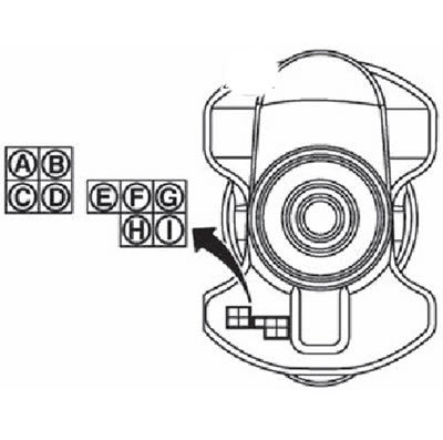
A. The size group of the connecting rod neck No. 1.
B. The size group of the connecting rod neck No. 2.
C. The size group of the crankpin No. 3.
D. Crankpin size group #4.
E. Size group of the root neck No. 1.
F. Size group of the root neck No. 2.
G. Size group of the root neck No. 3.
N. Dimensional group of the root neck No. 4.
I. Size group of the root neck No. 5.
3. Determine the symbol at the intersection of the selected row and column in «Selection table for main bearing shells».
Attention.
- There are two tables for selecting main bearing shells. The first is designed for the necks of the main bearings No. 1, 4 and 5. The second is for the necks of the main bearings No. 2 and No. 3. For the selection of liners, use the tables for the indicated necks.
- Do not confuse tables.
4. According to the received symbol, select the root bearings of the required thickness.
Note. Main bearing shells are supplied as a set of upper and lower bearings.
When using a used cylinder block and crankshaft
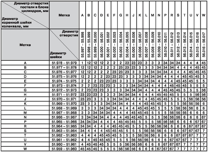
1. Measure separately the diameters of the crankshaft main journal and the bed bore in the cylinder block.
2. Use the obtained results for «Selection tables for main bearing shells».
3. Determine the symbol at the intersection of the selected row and column in «Selection table for main bearing shells».
Attention.
- There are two tables for selecting main bearing shells. The first is designed for the necks of the main bearings No. 1, 4 and 5. The second is for the necks of the main bearings No. 2 and No. 3. For the selection of liners, use the tables for the indicated necks.
- Do not confuse tables.
4. According to the received symbol, select the root bearings of the required thickness.
Note. Main bearing shells are supplied as a set of upper and lower bearings.
Selection table for main bearing shells (necks No. 1, 4 and 5)
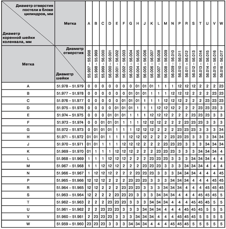
Selection table for main bearing shells (necks No. 2 and 3)
Note. See section «Service data and specification» at the end of the chapter.
Using Indigenous Bearings of Size Groups
In the case when, when using liners of standard size groups, the specified value of the oil clearance is not provided, liners of repair size groups should be used.
Measure the diameter of the main bearing hole in the cylinder block with the liners installed and regrind the crankshaft main journal to provide the required clearance.
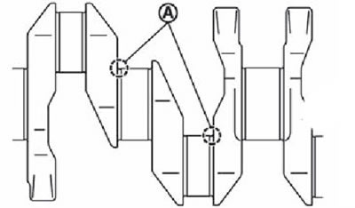
Attention. When grinding the neck for repair inserts, it is necessary to ensure the radius of the fillets (A) equal to 1.5-1.7 mm.