When using a new connecting rod and crankshaft
1. Determine the size group of the diameter of the hole of the lower head of the connecting rod according to the mark you stamped on the side surface to select the line «Conrod bearing selection tables».
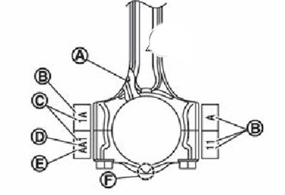
A. Oil hole.
B. Factory code.
C. Cylinder number.
D. Connecting rod hole size group.
E. size group of the hole of the upper head of the connecting rod.
F. Front mark.
2. Determine the size group of the connecting rod journal of the crankshaft by the stamp on the front side of the crankshaft to select the column «Conrod bearing selection tables».
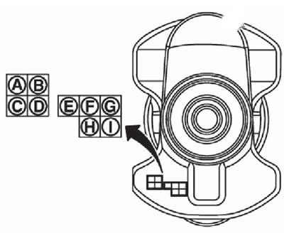
A. The size group of the connecting rod neck No. 1.
B. The size group of the connecting rod neck No. 2.
C. The size group of the crankpin No. 3.
D. Crankpin size group #4.
E. Size group of the root neck No. 1.
F. Size group of the root neck No. 2.
G. Size group of the root neck No. 3.
N. Dimensional group of the root neck No. 4.
I. Size group of the root neck No. 5.
3. Determine the symbol at the intersection of the selected row and column in «Conrod bearing selection table».
4. According to the received symbol, select the connecting rod bearings of the required thickness.
When using used connecting rods and crankshaft
1. Measure separately the diameters of the connecting rod journal of the crankshaft and the hole of the lower head of the connecting rod.
2. Use the obtained results for «Conrod bearing selection tables».
3. Determine the symbol at the intersection of the selected row and column in «Conrod bearing selection table».
4. According to the received symbol, select the connecting rod bearings of the required thickness.
Conrod bearing selection table
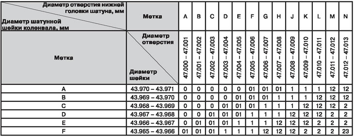
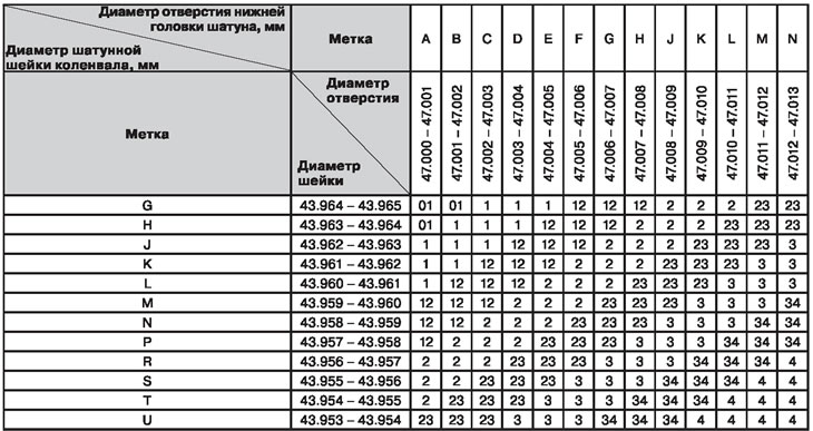
Note. See section «Service data and specification» at the end of the chapter.
Using connecting rod bearings of size groups
In the case when, when using liners of standard size groups, the specified value of the oil clearance is not provided, liners of repair size groups should be used.
Measure the bore diameter of the connecting rod bottom end with bearings installed and regrind the crankshaft journal to provide the correct clearance.
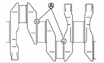
Attention. When grinding the neck for repair inserts, it is necessary to ensure the radius of the fillets (A) equal to 1.5-1.7 mm.