Note. Standard values for all checks are given in the section «Service data and specification» at the end of the chapter.
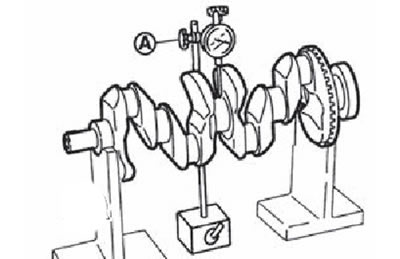
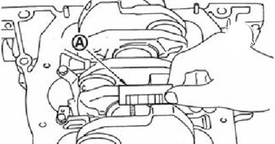
Checking the axial clearance of the crankshaft
Using a dial indicator (A), measure the crankshaft axial clearance by moving the crankshaft forward and backward as far as it will go with a screwdriver.
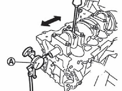
If the value obtained exceeds the maximum allowable value, replace the thrust half rings and re-measure. If the end play still exceeds the limit, replace the crankshaft with a new one.
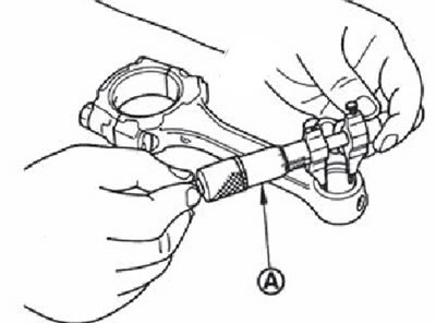
Checking the side clearance of the connecting rod
Measure the side clearance between the connecting rod and the crankshaft web using a set of flat feeler gauges (A).
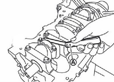
If the value obtained exceeds the limit, replace the connecting rod and re-measure. If the backlash still exceeds the limit, replace the crankshaft.
Gap between piston and piston pin
Piston pin hole diameter
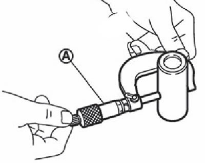
Using a micrometer (A), measure the inside diameter of the piston pin bore.
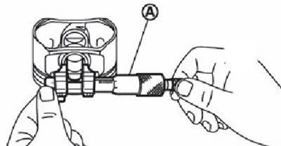
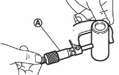
Piston pin outer diameter
Micrometer (A) measure the outside diameter of the piston pin.
Gap between piston and piston pin
(Gap between piston and piston pin) = (Piston bore diameter) - (Piston pin diameter)
If the clearance value obtained is not correct, replace the piston and piston pin as a set.
Note.
- When replacing a piston with a pin assembly, follow the piston selection information (see below).
- Only piston pins differ in size groups (holes in the piston), selectively selected at the factory. There are no size groups for piston pins available as spare parts (supplied only "zero" size group).
Piston ring side clearance
Measure the backlash between the piston rings and the grooves in the piston using a set of flat feeler gauges (A).
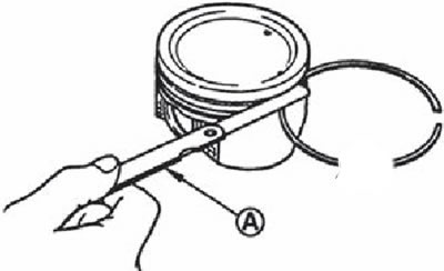
If the value obtained exceeds the limit, replace the piston ring and remeasure. If the clearance still exceeds the limit, bore the cylinder and use an oversized piston and piston rings.
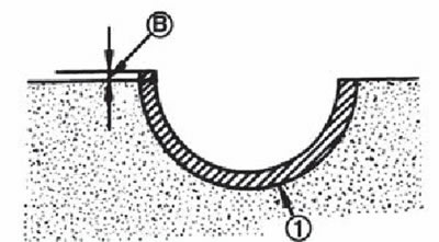
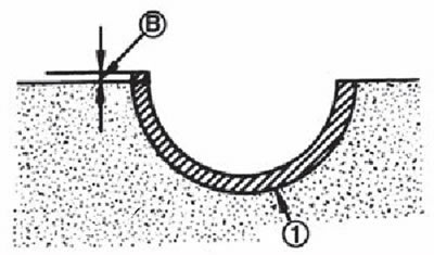
Piston ring gap
Verify that the inner bore diameter of the cylinder is within specification (see "Clearance between piston and cylinder" below).
Lubricate the piston (1) and piston ring (2) fresh engine oil, then use the piston to push the piston ring (A) to the middle of the cylinder (IN), and measure the clearance in the piston ring lock with a flat feeler gauge (WITH).
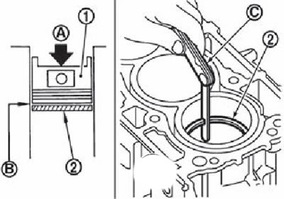
If the measured value exceeds the limit value, replace the piston ring and measure again. If the measurement still exceeds the limit, bore the cylinder bore and use oversize pistons and piston rings.
Bending and twisting of the connecting rod
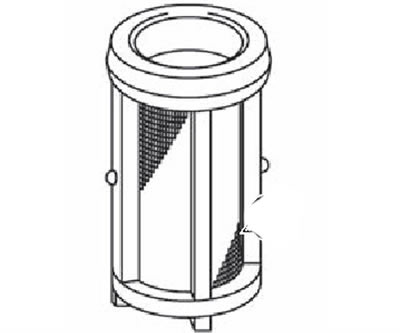
Check the geometric parameters of the connecting rod using a specially designed stand.
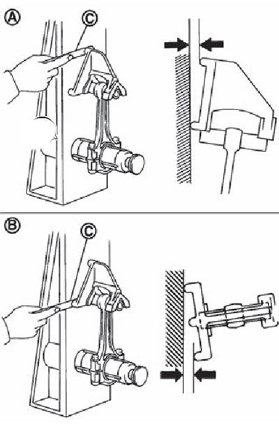
A. Bend.
B. Torsion.
C. Flat feeler set.
If the obtained parameters exceed the maximum permissible values, replace the connecting rod with a new one.
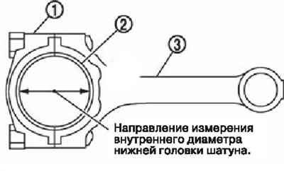
Connecting rod diameter
Install the connecting rod cover (1) without connecting rod bearing and tighten the connecting rod bolts to the specified torque.
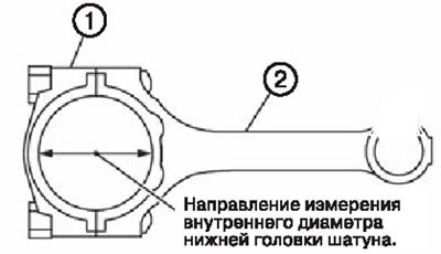
1. Connecting rod cap.
2. Connecting rod.
Measure the inside diameter of the bottom end of the connecting rod using an inside gauge.
If the value obtained exceeds the limit, replace the connecting rod assembly.
Clearance in the upper head of the connecting rod
Connecting rod inner diameter
Using a micrometer with an inside gauge (A), measure the inside diameter of the connecting rod bush.
Piston pin outer diameter
Micrometer (A) measure the outside diameter of the piston pin.
Clearance in the upper head of the connecting rod
(Clearance in the upper head of the connecting rod) = (Connecting Rod Bushing Inner Diameter) - (Piston pin outer diameter)
If the gap value obtained is not correct, replace the connecting rod assembly and/or the piston and piston pin assembly.
When replacing a piston with a pin assembly, follow the piston selection information (see below).
When replacing a connecting rod, follow the information on the selection of connecting rod bearings (see below).
Non-flatness of the upper surface of the cylinder block
Using a scraper, remove the remaining gasket from the upper surface of the cylinder block, and also clean the surfaces of oil, carbon deposits and other contaminants.
Attention. Be careful not to allow gasket residue to enter the oil and coolant channels in the cylinder block.
With a straightedge (A) and a set of flat probes (IN) measure the flatness of the surface of the cylinder block at several points in six directions.
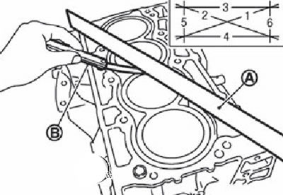
If the measured value is not correct, replace the cylinder head with a new one.
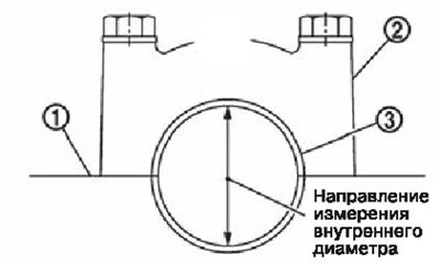
Inner diameter of the bed of main bearings
Install the main bearing caps without shells and tighten the mounting bolts to the specified torque.
Measure the inside diameter of the main bearing bed with a bore gauge.
Measurement to be made in the plane indicated in the figure (5 mm from the leading edge of the main bearing bed) in two directions. For analysis, choose the smallest of the two obtained diameter values.
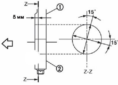
1. Cylinder block.
2. Main bearing cap.
The arrow points towards the front of the engine.
If the value obtained is not correct, replace the cylinder block with main bearing cap assembly.
Note. Main bearing caps are not subject to separate replacement, as they are bored together with the cylinder block.
Clearance between piston and cylinder
Cylinder Bore Inner Diameter
Using a caliper (A), measure the diameters of the cylinder bore in various planes and directions to determine the amount of wear, ovality and taper of the cylinder (directions «X» And «Y» in planes «A», «IN» And «WITH»; «Y» - longitudinal direction relative to the engine).
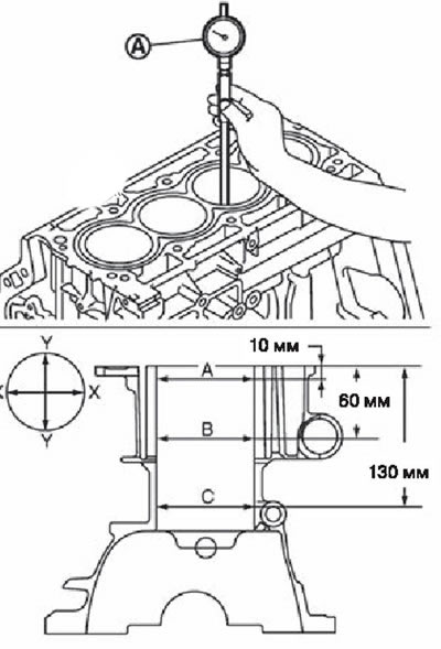
Note. To determine the size group of the cylinder bore, measure the diameter of the cylinder in the direction «X» in plane «IN».
If the values obtained exceed the maximum allowable values, or if there are scratches and / or burrs on the cylinder mirror, replace the cylinder block with a new one.
Note. The use of oversized pistons is not allowed.
Skirt diameter
Micrometer (A) measure the outside diameter of the piston skirt.
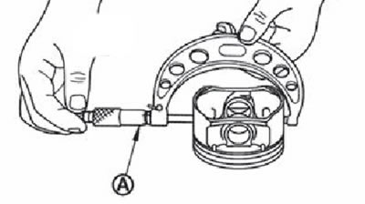
Clearance between piston and cylinder
Using the measured values of the cylinder diameter and piston skirt, calculate the gap value (direction "X", plane "IN").
(Gap) = (Cylinder diameter) - (Skirt diameter).
If the value obtained is greater than the limit, replace the piston and piston pin assembly and/or cylinder block.
Diameter of the bearing journal of the crankshaft
Measure the outside diameter of the crankshaft bearing journal with a micrometer (A).
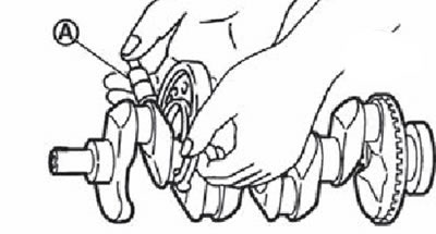
If the value obtained is not correct, measure the main bearing clearance and use oversized main bearing shells.
Diameter of the connecting rod journal of the crankshaft
Measure the outer diameter of the crankshaft journal with a micrometer.
If the value obtained is out of specification, measure the clearance in the connecting rod bearing and use oversized connecting rod bearings.
Ovality and taper of crankshaft journals
Using a micrometer, measure the diameter of each main and connecting rod journal at four points on the crankshaft journal as shown in the figure.
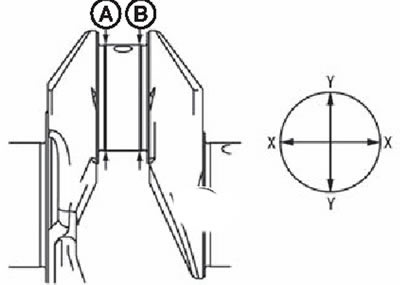
Out-of-roundness is defined as the difference in diameter between directions «X» And «Y» in planes «A» And «IN».
Taper is defined as the difference in diameter between planes «A» And «IN» in directions «X» And «Y».
If the obtained values exceed the maximum permissible values, regrind or replace the crankshaft.
After regrinding, measure the clearances in the main and connecting rod bearings, and then select the liners of the main and / or connecting rod bearings.
Runout of the crankshaft
Install the prisms but the marking plate and put the crankshaft on the prisms.
Install a dial indicator on the middle main journal (№ 3).
Rotating the crankshaft, measure the runout of the crankshaft along the middle main journal (full amplitude of movement of the arrow).
If the value obtained exceeds the limit, replace the crankshaft with a new one.
Gap in connecting rod bearings
Estimated clearance definition
Install connecting rod bearings (2) into the connecting rod (3) and connecting rod cover (1), then tighten the connecting rod bolts to the specified torque.
1. Connecting rod cap.
2. Connecting rod.
Using a micrometer with an inside gauge, measure the inside diameter of the hole in the bottom end of the connecting rod.
(Gap) = (Connecting rod bore diameter) - (Crankpin diameter)
If the gap exceeds the maximum allowable value, select suitable connecting rod bearings based on the diameter of the hole in the lower head of the connecting rod, the diameter of the connecting rod journal and the required oil clearance.
Measuring the gap with a calibrated wire
Thoroughly wipe the connecting rod neck of the crankshaft and the connecting rod bearings.
Measure and cut the calibrated Plastigage plastic wire to a length slightly less than the width of the liner and install along the neck, but not over the oil hole.
Install the connecting rod bearings in the connecting rod and in the connecting rod cap, tighten the nuts to the specified torque.
Attention. Do not turn the crankshaft.
Remove the connecting rod cover with the bushing and measure the width of the wire in the most flattened part, and then determine the value of the radial oil clearance using the gauge scale.
Note. If the gap is greater than the maximum, the measures taken are the same as in the case of the calculation method.
Clearance in main bearings
Estimated clearance definition
Install main bearing shells (3) into the cylinder block (1) and main bearing cap (2), then tighten the cover bolts to the specified tightening torque.
Measure the inside diameter of the main bearing with a bore gauge.
(Clearance in the main bearing) = (Main bearing inner diameter) - (Crankshaft journal diameter)
If the value obtained exceeds the maximum allowable value, select a suitable diameter of the main bearing shells and crankshaft main journals to provide the necessary clearance in the main bearings.
Measuring the gap with a calibrated wire
Thoroughly clean the crankshaft journal and main bearing shells.
Measure and cut the calibrated Plastigage plastic wire to a length slightly less than the width of the liner and install along the neck, but not over the oil hole.
Install the main bearing shells in the cylinder block and main bearing cap, tighten the mounting bolts to the specified torque.
Attention. Do not turn the crankshaft.
Remove the main bearing cap with bushing and measure the width of the wire in the most flattened part, and then determine the value of the radial oil clearance using the gauge scale.
Note. If the gap is greater than the maximum, the measures taken are the same as in the case of the calculation method.
Protrusion height of the main bearing shell
After removing the root cover with the liner (1), the bolts of which have been tightened to the specified torque, the end of the bushing must protrude (IN) above the bed connector.
If there is no protrusion, replace the bearings.
Conrod bearing protrusion height
After removing the connecting rod cap with bearing (1) (connecting rod bolts have been tightened to the specified torque) the end of the insert should protrude (IN) above the bed connector.
If there is no protrusion, replace the bearings.
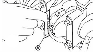
Outer diameter of main bearing cap bolts
Measure outer diameter ("d1", "d2") at two points as shown in the figure.
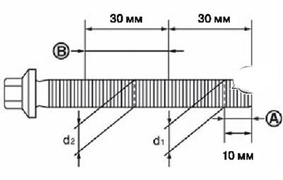
A: measuring point "d1".
B: fine measurement "d2".
If the bolt thinning does not occur at the point indicated in the figure "d2", and in the other, then this point must be considered as "d2".
Note. Maximum allowable difference ("d1"-"d1"): 0.15 mm.
If the difference between the two diameters exceeds the limit, replace the main bearing cap bolt with a new one.
Outer diameter of connecting rod bolts
Measure outer diameter «d» at the point indicated in the figure.
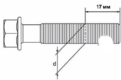
If the bolt thinning does not occur at the point indicated in the figure "d1", and in the other, then this point must be considered as "d1".
Note. Maximum allowable diameter: 7.75 mm.
If the obtained value of the diameter of the connecting rod bolt exceeds the maximum allowable value (the bolt is too thin), replace the connecting rod bolt with a new one.
Clogging or damage to the oil filter of the intake valve timing control system
Check the oil filter for foreign material and check for clogging. Clean the filter if necessary.
Check the oil filter for damage. Replace if necessary.
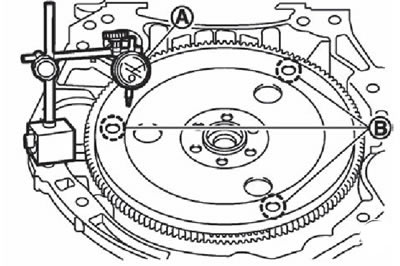
Flywheel deformation (modifications with a manual transmission)
With a dial indicator (A) measure the amount of deformation of the contact surface of the flywheel (turn the flywheel).
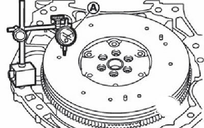
Note.
- Measurement to be made on a diameter of 210 mm.
- Maximum permissible deformation of the contact surface of the flywheel: no more than 0.45 mm.
If the measured value is not correct, replace the flywheel.
If signs of burning or discoloration are found on the surface, remove them with sandpaper.
Attention. Do not allow the magnate to be in close proximity during the measurement (on the dial indicator stand) with impulse disc on the back of the crankshaft.
Flywheel play (modifications with a manual transmission)
Attention. Do not dismantle a flywheel with twin masses.
Flywheel play in axial direction (back and forth)
Measure the axial play (back and forth) when applying a force of 100 N (10.2 kg) within a radius of 125 mm from the center of the flywheel.
Note. Standard value of axial play: no more than 1.8 mm.
If the value obtained is not correct, replace the flywheel with a new one.
Circumferential play (twisting)
Check the amount of play around the circumference:
1. Insert the clutch pressure plate mounting bolt (1) into the mounting hole and place the torque wrench (A) along the center line of the flywheel (2).
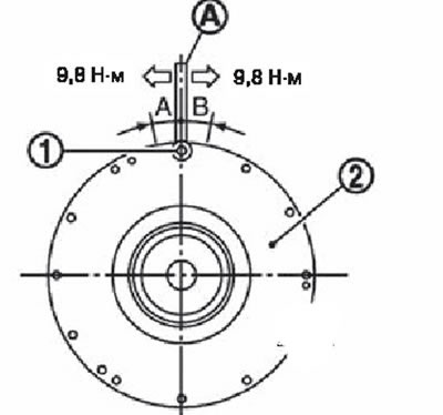
Note. Tighten the bolt to a torque of 9.8 Nm to prevent it from turning unintentionally.
2. Make alignment marks around the circumference of the two flywheel masses without applying any load.
3. Applying a force of 9.8 Nm in each direction and note the value in relation to the displacement of the masses on the side of the gearbox.
4. Measure the amount of relative displacement «A» And «IN» around the flywheel on the gearbox side.
Note. Maximum permissible value: no more than 33.2 mm.
If the measured value is not correct, replace the flywheel with a new one.
Deformation of the drive disc (modifications to the variator)
Measure the amount of deformation of the contact surface of the driving disk using a dial indicator (A) (rotate the drive).
Note.
- Measurement to be made in the area limited by the diameter of 12.4 mm and 20.0 mm around the hole (IN).
- The maximum permissible value of deformation: on whiter 0.35 mm.
If the measured value is not correct, replace the drive disc with a new one.