2. Remove the thermostat housing.
3. Remove the knock sensor.
Attention. Do not drop or strike the knock sensor.
4. Remove the sensor cover and crankshaft position sensor.
Attention.
- Do not drop or strike the crankshaft position sensor.
- Do not disassemble the crankshaft position sensor.
- Do not expose the crankshaft motion sensor to an electromagnetic field.
5. Remove the oil filter of the intake valve timing control system.
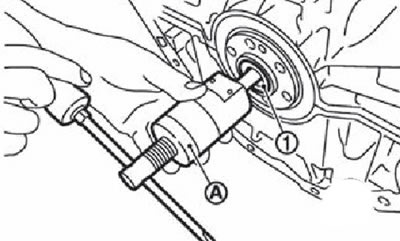
6. Variator versions: remove converter guide (1) using a special puller (ST16610001) (A) or the right tool.
Note. Manual transmission versions do not have a transducer guide.
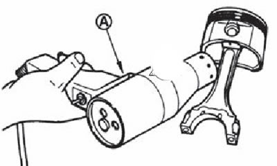
7. Remove pistons with connecting rods assembly:
Note. Before removing pistons with connecting rods as an assembly, weld the side clearances of the connecting rods.
Place the corresponding crankshaft crankpin in the appropriate position so that the connecting rod with the piston to be removed is in the bottom dead center position.
Remove the connecting rod cover.
Use a wooden hammer handle or similar tool to push the piston and connecting rod assembly toward the cylinder head.
Attention.
- Be careful not to damage the connecting rod and connecting rod cap mating surfaces.
- Be careful not to damage the cylinder bore and crankshaft journal with the bottom edge of the connecting rod.
8. Remove connecting rod bearings.
Note. Arrange the removed connecting rod bearings in order according to the cylinder numbers for correct installation during reassembly.
C. Remove the piston rings from the piston using the special tool (A).
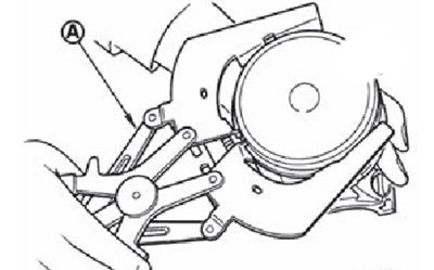
Note. Before removing the piston rings, check their side clearance on the piston.
When removing the piston rings, be careful not to damage the piston.
Be careful not to damage the piston rings due to excessive expansion.
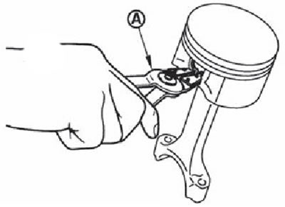
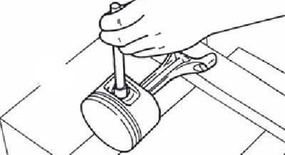
10. Separate the piston and connecting rod:
With a special tool (A) remove the lock pin circlips.
Heat the piston to a temperature of 60-70°using an industrial hair dryer (A) or in some other way.
Press out the piston pin with a rod with a diameter of about 18 mm.
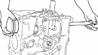
11. Using a TORX bit (size E14), unscrew the bolts securing the main bearing caps in the reverse order shown in the figure.
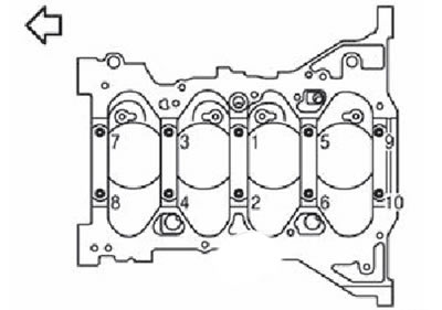
The arrow points towards the front of the engine
Note. Before loosening the bolts of the main bearing caps, measure the axial play of the crankshaft.
12. To remove covers of radical bearings of a cranked shaft.
Note. To remove the main bearing caps, lightly tap them with a plastic hammer.
Attention. Be careful not to damage the contact surfaces.
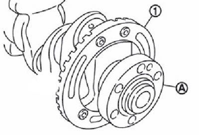
13. Remove the crankshaft.
Attention.
- Be careful not to damage or deform the impulse disk (1), mounted at the rear of the crankshaft (A).
- In order to lay the crankshaft on a flat surface, a wooden block must be used to prevent the impulse disc from contacting the surface.
- Do not remove the impulse disk unless absolutely necessary.
Note. To remove or install the impulse disk, use the TORX socket (size T30).
14. Remove the oil seal from the rear of the crankshaft.
15. To take loose leaves of radical bearings and persistent half rings from the block of cylinders and covers of radical bearings.
Note. Arrange the removed bushings and thrust washers in order according to the cylinder numbers for correct installation during reassembly.