Attention. Use goggles for eye protection.
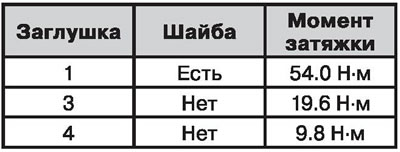
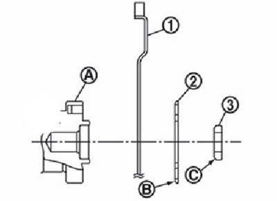
2. Install all plugs in the cylinder block as shown.
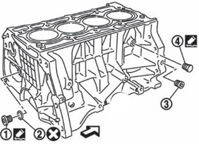
The arrow points towards the front of the engine
1. Plug at the back of the unit.
2. Washer.
3. A plug of a forward part of the block of cylinders.
4. Drain plug.
Note.
: replace the part with a new one after each removal.
: where to apply the sealant.
- Apply sealant to the threads of the plug (4) drain hole. Use original sealant or equivalent.
- Apply sealant to the threads of the plug (1). Use threadlocker or equivalent.
- Apply sealant to the plug (3).
- Tighten the plugs to the specified tightening torques given in the table below.
3. Install the main bearing shells and thrust washers:
Remove dust, dirt and engine oil from the surface of the seats in the cylinder block and main bearing caps.
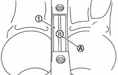
Install thrust washers on both sides of main bearing seat #3 (IN) in the cylinder block.
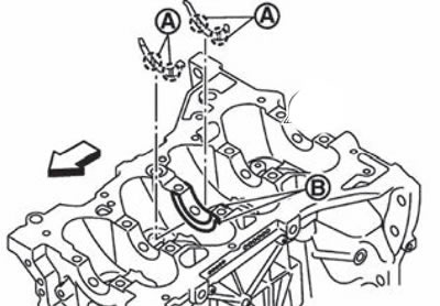
The arrow indicates the side of the front of the block
Note. Install the thrust washers so that the oil grooves (A) were directed outward.
Install the main bearing shells, paying special attention to the direction of installation.
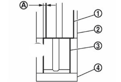
1. Main bearing shell.
2. Block of cylinders.
3. Lower main bearing shell.
4. Main bearing cap.
Note.
- Before installing the main bearing shells, apply fresh engine oil to the inside surface of the bearing shell. Do not apply oil to the back surface, but clean it thoroughly.
- When installing, place the main bearing shell exactly in the center of the seat in the cylinder block or bearing cap.
- Bias (A) relative to the top (1) and lower (3) main bearing shells should not exceed 0.85 mm.
- Make sure the oil holes (A) in the cylinder block and in the liner (1) match up.
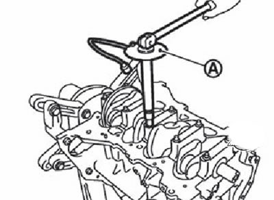
4. If it was removed, install the impulse disk on the crankshaft:
Install the impulse disk with the flange towards the front of the engine on the rear of the crankshaft.
Apply fresh engine oil to the threads and seating surfaces of the mounting bolts.
Install impulse drive (1) on the crankshaft (2), guided by the hole (A) for the locating pin, then tighten the mounting bolts in the sequence shown in the figure using a TORX socket.
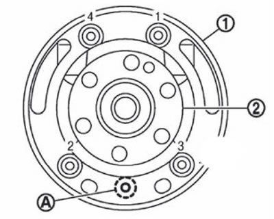
Note. A crankshaft locating pin and an impulse disk are supplied as a spare part with each of them.
Tighten the mounting bolts in the sequence shown in the figure.
Remove dowel pin.
Attention. Make sure the dowel pin is removed.
5. Install the crankshaft in the cylinder block.
Note. Make sure the crankshaft rotates freely by hand.
6. Install the main bearing caps:
Install the main bearing caps, guided by the stamp (A) number and front label (IN).
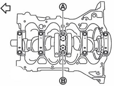
The arrow points towards the front of the engine
Note. The main bearing caps are not replaced as separate spare parts as they are bored together with the cylinder block.
Tighten the bolts of the main bearing caps in the sequence shown in the figure in several stages:
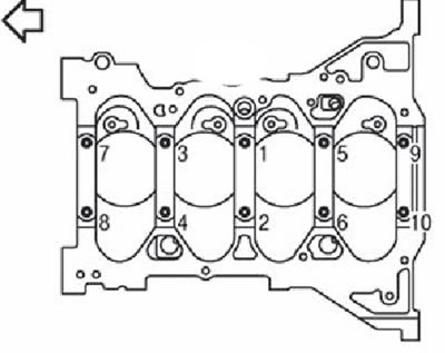
The arrow indicates the side of the front of the engine
1) Apply fresh engine oil to the threads and seating surfaces of the mounting bolts.
2) Tighten the main bearing cap bolts to 34.3 Nm.
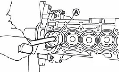
3) Tighten the main bearing cap bolts 60°clockwise (stretching to the corner) in the sequence shown in the figure.
Attention. Tightening to an angle is carried out using an angle wrench (KV10112100) (A). Do not tighten bolts «approximately».
Note.
- After tightening the main bearing cap bolts, check that the crankshaft is still free to rotate.
- Check crankshaft end play.
7. Connect the pistons to the connecting rods:
Using the special tool, install a new circlip into the groove at the back of the piston.
Note. Make sure the circlip is fully seated in the piston groove.
Install the piston on the connecting rod.
Using a heat gun, heat the piston to approximately 60-70°C so that the piston pin can be easily inserted by hand. Insert the piston pin into the piston with connecting rod through the front hole in the piston.
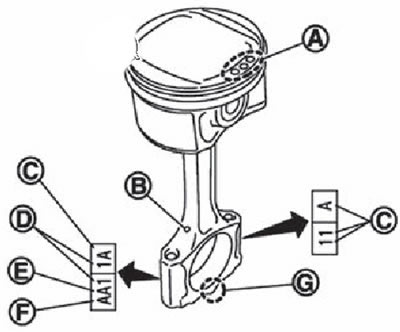
Make sure the front mark (A) on the piston crown and oil hole (IN), as well as the number of the cylinder (D) on the connecting rod are in the position shown in the figure.
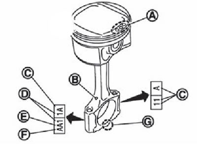
A. Front mark.
B. Oil hole.
C. Factory code.
D. Cylinder number.
E. The size group of the diameter of the lower head of the connecting rod.
F. Connecting rod top diameter size group.
G. Connecting rod cover front mark.
Install a new circlip into the groove on the front of the piston.
Note.
- Make sure the circlip is fully seated in the piston groove.
- After installation, make sure that the connecting rod moves freely.
8. Using a piston ring remover, install the piston rings.
Attention.
- Be careful not to damage the piston.
- Be careful not to damage the piston rings due to excessive expansion.
Note. Install the piston rings so that their locks are in the position shown in the figure.
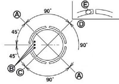
A. The lock of the upper or lower oil scraper disk.
B. Front mark.
C. The lock of the second compression and expansion oil scraper rings.
D. Upper compression ring lock.
E. Stamp.
Attention. Do not align the gap in the lock of the oil scraper discs of the oil scraper ring with the oil groove of the piston.
Note. Install the second compression ring so that the stamped surface (E) was directed upward.
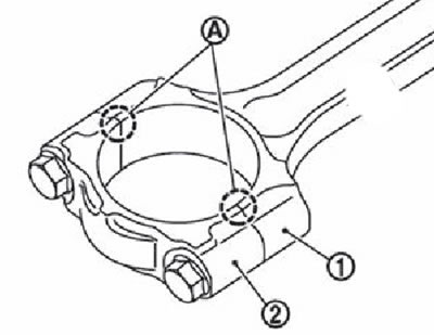
9. Install top (2) and lower (3) connecting rod bearings in the connecting rod (1) and connecting rod cover (4).
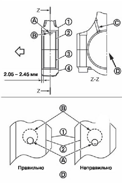
A. Oil hole.
B. Oil hole cone in connecting rod.
C. Oil hole in connecting rod.
D. View from the side of the arrow.
The arrow points towards the front of the engine.
Install the connecting rod bearings as shown.
Make sure the oil hole (A) completely in the cone (D) connecting rod oil hole.
When installing connecting rod bearings, apply fresh engine oil to the inner surfaces. Do not apply engine oil to the back surfaces of the liners, but clean them thoroughly.
Note.
- The connecting rod bearings do not have positioning lugs.
- Connecting rod bearings must be installed in the center of the connecting rod and connecting rod cap, as shown in the figure. For service operations, the center position can be determined visually.
10. Install the piston with connecting rod assembly on the crankshaft.
Set the corresponding crankshaft crankpin to bottom dead center.
Apply a sufficient amount of fresh engine oil to the cylinder bore, piston and crankpin.
Set the correspondence of the piston with the connecting rod to a particular cylinder according to the number label (D) on the rod.
A. Front mark.
B. Oil hole.
C. Factory code.
D. Cylinder number.
E. The size group of the diameter of the lower head of the connecting rod.
F. Connecting rod top diameter size group.
G. Connecting rod cover front mark.
Position the piston with the connecting rod so that the front (A) but the bottom of the piston was directed towards the front of the engine.
Using a piston ring compressor (A) (EM03470000) or a suitable tool, insert the piston with connecting rod into the cylinder bore.
Attention. Be careful not to damage the cylinder bore and crankshaft journal with the bottom of the connecting rod.
11. Install the appropriate connecting rod cap, referring to the cylinder number mark.
12. Tighten connecting rod bolts.
Attention. Make sure that there are no protrusions on the thrust joint surface (A) between connecting rod (1) and connecting rod cover (2), as well as the correct installation of the connecting rod bearings. Then tighten the connecting rod bolts.
Attention. If connecting rod bolts are reused, measure their diameter (see «Check after disassembly»).
Apply fresh engine oil to the threads and seating surfaces of the connecting rod bolts.
Tighten bolts to 27.4 Nm.
Loosen screws completely.
Tighten the connecting rod bolts again to 19.6 Nm.
Tighten the bolts by 60" clockwise (dotyazhka but angle).

Attention. Use a special corner wrench to tighten the corner (KV10112100). Do not tighten bolts «approximately».
Note.
- After tightening the connecting rod bolts, check that the crankshaft rotates freely.
- Check the side clearance of the connecting rod.
13. Install oil pans (upper and lower).
Note. After installing the upper oil pan, the rear oil seal must be installed.
14. Install the rear oil seal.
15. Install drive disc (1) (modifications with a variator!) or flywheel (modifications with a manual transmission).
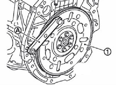
Note. Fix the crankshaft with a locking plate (KV11105210) (A), then tighten the mounting bolts in several approaches in a cross pattern.
Note. Lead disk. Install drive disk (1), reinforcing disk (2) and guide bushing. Using a mandrel with a diameter of 33 mm, press the guide sleeve into the end of the crankshaft until it stops.
A. Rear of the crankshaft.
B. Rounding.
S. Chamfer.
Note. Models with a manual transmission do not have a guide bush and a reinforcing disk.
16. Install knock sensor.
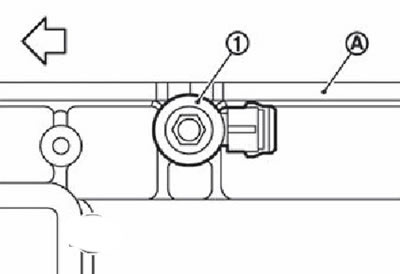
A. Left side of cylinder block. The arrow points towards the front of the engine
Note. Install knock sensor (1) with the wire connector facing towards the rear of the engine.
Attention.
- Do not tighten the sprinkling bolt while holding the sensor by the wire connector.
- If the sensor has been dropped or subjected to impact, it must be replaced with a new one.
Note.
- Make sure that there are no foreign materials on the mounting surface of the cylinder block and the rear surface of the knock sensor.
- Make sure the knock sensor is not touching other parts.
17. Install the crankshaft position sensor (P0S) and sensor cover.
Attention.
- Handle the sensor carefully, do not drop it or hit it.
- Do not disassemble the sensor.
- Do not expose the crankshaft position sensor to an electromagnetic field.
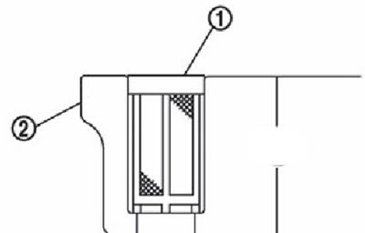
18. Install the oil filter of the intake valve timing control system (1) in the position shown in the figure.
Note. After installation, make sure that the oil filter does not protrude from the top surface of the cylinder block (2).
19. Further assembly is carried out in the reverse order of disassembly.