


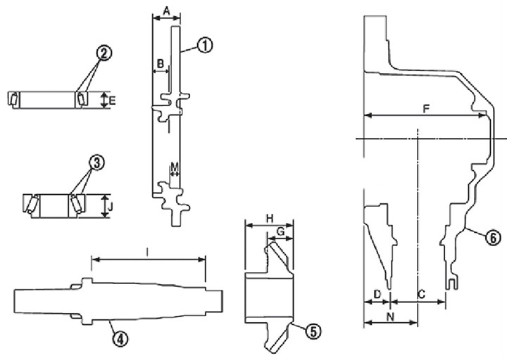
Measurement parameters:
1. Adapter case.
2. Ring gear shaft bearing (from the transition housing).
3. Ring gear shaft bearing (from the crankcase side of the transfer case).
4. Ring gear shaft.
5. Ring gear.
6. Carter transfer case.
Ring gear adjustment gasket (adapter case side)
1. Measure all required dimensions as follows:
Size "A"
With the help of a caliper and a straightedge, measure the distance from the contact surface of the adapter housing with the transfer case housing to the extreme surface of the adapter housing (see picture "Measurement parameters" higher).
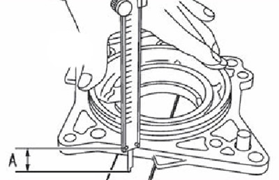
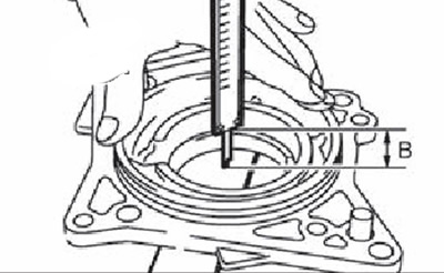
Size "IN"
Using the Circulation Test and a straightedge, measure the distance from the ring gear shim seating surface on the adapter case to the outermost surface of the adapter case (see picture "Measurement parameters" higher).
Size "WITH"
Using a vernier caliper, measure the diameter of the installation area of the pinion shaft bearing (backside) in the transfer case (see picture "Measurement parameters" higher).
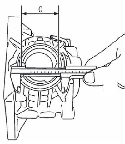
Attention. Be careful not to damage the crankcase of the transfer box.
Size "D"
Using a vernier caliper and a straightedge, measure the distance from the contact surface of the transfer case housing with the adapter housing to the mounting surface of the vape gear bearings (backside) (see picture "Measurement parameters" higher).
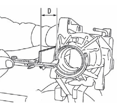
Attention.
- Be careful not to damage the transfer case housing.
- Observe the thickness of the straight edge.
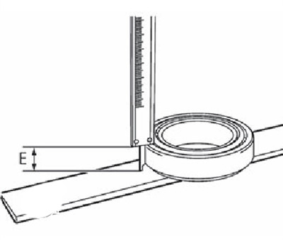
Size "E"
Using a dial gauge, measure the distance from the outer surface of the bearing ring of the ring gear shaft (adapter case side) to the extreme surface of the inner ring (si. drawing "Measurement parameters" higher).
2. Calculate dimensions "M" And "N" according to the following formula:
- M = A - B
- N \u003d C x 0.5 + D
3. Convert the E, M and N rezirrs according to the following standards:
- E: Actual value relative to a range of 0 to 20.00 mm in 0.01 mm increments.
- M: Actual value relative to a range of 0 to 13.90 mi in 0.01 mm increments.
- N: Actual value relative to a range of 0 to 55.00 mm in 0.01 mm increments.
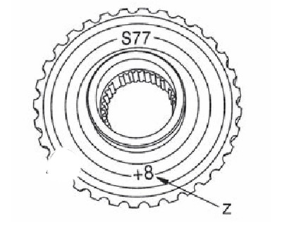
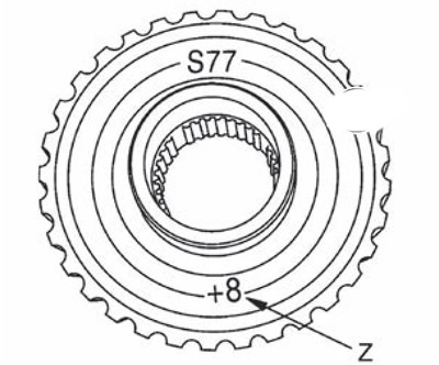
4. Check size "Z" (processing tolerance) on the back surface of the ring gear.
Note. Size "Z" indicates the difference between the optimal engagement and the standard size in increments of 0.01 mm, which is indicated by the corresponding inscription on the back side of the ring gear.
5. Calculate the thickness of the ring gear shim (adapter case side) T1 according to the following formula:
- T1= (M + N - E - Z) x 0.01 + 1.40 mm
6. Select ring gear shim (adapter case side).
Attention.
- Use only one adjustment gasket.
- If there is no shim of the desired thickness, it is necessary to select a shim, the thickness of the copra is closest to the calculated value, and it is preferable to shim a little thicker than the desired value than thinner.
Ring gear adjustment gasket (transfer case housing side)
1. Measure all required dimensions as follows:
Size "WITH"
Using a caliper, measure the diameter of the installation area of the pinion shaft bearing (backside) in the transfer case (see picture "Measurement parameters" higher).
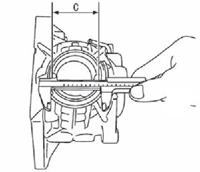
Attention. Be careful not to damage the transfer case housing.
Size "D"
With the caliper pump and straightedge, measure the distance from the contact surface of the transfer case housing with the adapter housing to the mounting surface of the gear shaft bearings (backside) (see picture "Measurement parameters" higher).
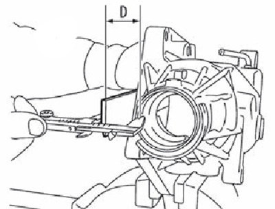
Attention.
- Be careful not to damage the transfer case housing.
- Observe the thickness of the straight edge.
Size "F"
Using a depth gauge, measure the distance from the contact surface of the transfer case housing with the adapter captepim to the mounting surface of the ring gear shim (see picture "Measurement parameters" higher).
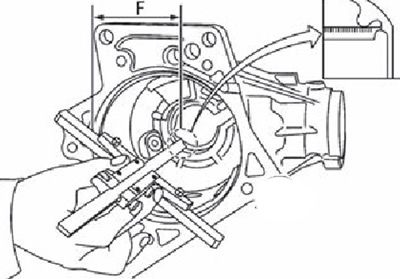
Attention. Be careful not to damage the transfer case housing.
Size "G"
Using a straightedge micrometer, measure the distance from the mounting surface of the ring gear shaft bearing to the lateral end surface of the transfer case housing (see picture "Measurement parameters" higher).
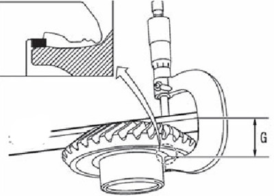
Attention. Observe the thickness of the straight edge.
Size "H"
When pumping the caliper, measure the distance from the outer surface on the side of the transfer case housing to the side surface on the side of the transition housing (see picture "Measurement parameters" higher).
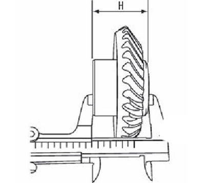
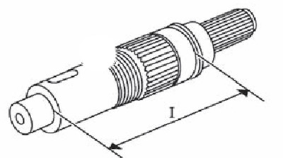
Size "I"
With a caliper pump, measure the distance from the ring gear seating surface on the ring gear shaft to the ring gear shaft bearing seating surface (transfer case housing side) (see picture "Measurement parameters" higher).
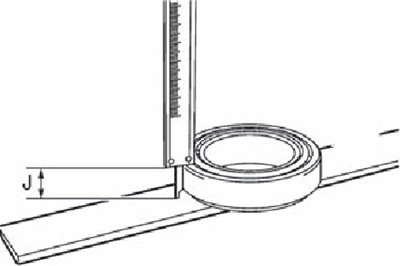
Size "J"
Using a caliper, measure the distance from the extreme surface of the outer ring of the ring gear shaft bearing (side of the transfer case caps to the extreme surface of the inner ring (see picture "Measurement parameters" higher).
2. Calculate size N using the following formula:
- N \u003d C x 0.5 + D
3. Convert dimensions F, G, H, I, J and N according to the following standards:
- F: Actual value relative to the range 0 to 122.60 mm in 0.01 mm increments.
- G: Actual value relative to a range of 0 to 26.60 mm in 0.01 mm increments.
- H: Actual value relative to a range of 0 to 48.60 mm in 0.01 mm increments.
- I: Actual value relative to the range 0 to 119.40 mm in 0.01 mm increments.
- J: Actual value relative to a range of 0 to 16.25 mm in 0.01 mm increments.
- N: Actual value relative to a range of 0 to 55.00 mm in 0.01 mm increments.
4. Check size "Z" (processing tolerance) on the back surface of the ring gear.
Size "Z" indicates the difference between the optimal mesh and the standard size in increments of 0.01 mm, which is indicated by the corresponding inscription on the back of the ring gear.
5. Calculate the thickness of the ring gear shim (adapter case side) T1 according to the following formula:
- T2 = (F - G + H - I - J - N + Z) x 0.01 + 1.65 mm
6. Select ring gear shim (adapter case side).
Attention.
- Use only one adjustment gasket.
- If there is no shim of the desired thickness, it is necessary to select a shim, the thickness of which is closest to the calculated value, and a shim slightly thicker than the desired value is preferable than thinner.
Adjusting lining of a shaft gear wheel
1. Check U dimensions (processing tolerance) between the old and new drive gears when replacing a pair of hypoid gears (pinion shaft and ring gear). Assemble new pinion shaft shims of the same thickness as those removed during disassembly, or remove pinion shaft shims when reusing a pair of hypoid gears.
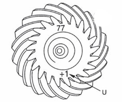
Note. Size "U" indicates the difference between the optimal engagement and the standard size in increments of 0.01 mm, which is indicated by the corresponding inscription on the end of the gear shaft.
2. Calculate the thickness of the T gear shaft shim using the following formula.
T = T0 + [ (t1 -12) x 0.01],
- where T: thickness of the new gasket.
- T0: old gasket thickness.
- t1: size "U", marked on the end of the old drive gear.
- t2: size "U", marked on the end of the new drive gear.
Note.
Example:
T= 3.21 + [ (2+1) x 0.01]
- Т0: 3.21
- t1: +2
- t2: -1
3. Select the gear shaft shim.
Attention.
- Use only one adjustment gasket.
- If a shim of the calculated thickness is not available, use the closest shim.