


Table of contents: Removal ↓ Installation ↓
Removal
1. Shift the transmission into neutral and release the parking brake.
2. Remove the main muffler and front exhaust pipe.
3. Apply alignment marks to the connecting flanges of the propeller shaft and the rear final drive.
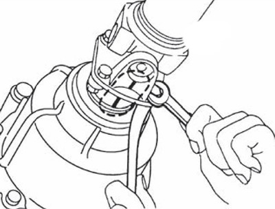
Attention. Use paint to apply installation marks. It is prohibited to damage the flange surface by punching, filing, etc.
4. Loosen the nuts securing the center bearing mounting bracket.
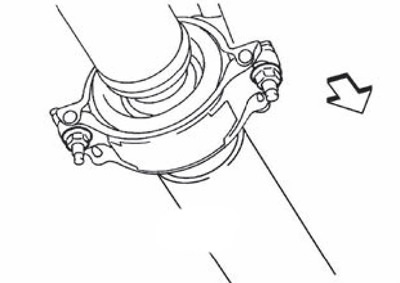
Note: The arrow in the illustration indicates the front of the vehicle.
Caution: Do not remove the nuts completely.
5. Loosen the bolts and nuts securing the cardan shaft.
6. Loosen the nuts securing the central bearing bracket.
7. Remove the propeller shaft assembly.
Caution: If the constant velocity joint is bent during removal, installation or transportation, its boot may be damaged. Wrap the area where the boot is inserted into the metal part with rags or rubber to protect the boot from damage.
8. Remove the clamps and remove the upper and lower center bearing mounting brackets.
Installation
Installation is carried out in the reverse order of removal, taking into account the following:
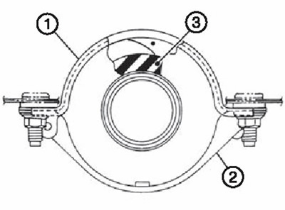
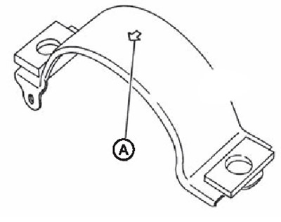
Install the upper center bearing mounting bracket (1) so that the mark in the form (A) faces forward.
 |
 |
Adjust the position of the center bearing mounting brackets (1 and 2) by moving them forward and backward to prevent axial play of the center bearing insulator (3). Install the mounting bracket (upper/lower) central bearing for a car.
When installing the cardan shaft, align the installation marks applied to the connecting flanges during removal.
For proper installation, it is necessary to adjust the position of the mounting bracket at the front and back to ensure there is no deformation (front-rear direction of the car) central bearing insulator.
After installation, perform a test drive to check for vibrations in the driveshaft. If vibrations are present, disconnect the driveshaft from the final drive. Reinstall the driveshaft by turning it 90 degrees, then repeat the test drive. If vibrations are still present, repeat the reinstallation of the driveshaft by turning it 90 degrees, up to turning it 270 degrees.
After tightening the bolts and nuts to the specified tightening torques, make sure that the bolts (3) on the flange side are tightened as shown in the figure.
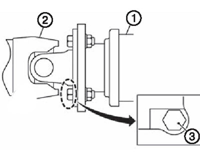
1. Main gear assembly.
2. Cardan shaft assembly.
3. Bolt.
If the propeller shaft assembly or the rear final drive assembly are being replaced with new ones, connect them as follows:
The text was borrowed from here [www.NissanBook.ru]
Position the connecting flange of the main gear (1) with the mark (A) facing upward. Connect the propeller shaft to the main gear so that the installation mark (B) of the propeller shaft (2) is located as close as possible to the installation mark (C) of the connecting flange of the main gear.
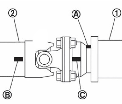
While pressing the cardan shaft, simultaneously tighten the connecting bolts and nuts of the cardan shaft and the main gear to the specified tightening torque.