Note. Maintenance of cardan joints is carried out in a complex. The repair kit includes a cross, four needle roller bearings with cups, oil seals and circlips. It is not recommended to disassemble the universal joints except for the replacement of components.
Attention! Do not clamp the propeller shaft sleeves or sliding joint too tightly in the vise to avoid irreversible deformation of the shells.
1. Remove the propeller shaft from the vehicle. Mark the installation position of the sliding joint and the spider flange holder in relation to the shaft body.
2. Separate the sliding half from the shaft.
3. Remove the grease fitting from the universal joint (if one is installed).
4. Using a pair of screwdrivers and a hammer, remove the bearing cup circlips from the cross holders.
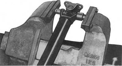
5. Clamp the hinged part of the shaft in a vise, placing interchangeable heads, on the one hand with an outer diameter slightly less than the ø of the cup, on the other - with an inner diameter slightly larger than the diameter of the cup (see accompanying illustration).
6. Squeeze the cup out of the holder until the cross rests against the wall of the latter.
7. Remove the shaft from the vise and remove the squeezed cup and needle rollers from the holder.
8. Again clamp a shaft in a vise and wring out a crosspiece in an opposite direction.
9. Remove the shaft from the vise and remove the opposite needle bearing cup and rollers.
10. Remove the sliding half or flange from the shaft.
11. Repeat the procedures of the last five paragraphs (for sliding shaft half or for flange), thereby completing the disassembly of the hinges (gimbal components shown in accompanying illustration).
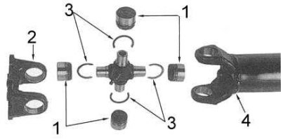
1 - needle roller bearings; 2 - flanged cross holder; 3 - retaining rings; 4 - holder of the cross from the side of the shaft
12. Clean the holes in the brackets of the holders, removing any burrs and roughness from their edges and walls.
13. Lubricate rollers and bearing cups with multipurpose grease.
14. Partially tuck one of the bearing cups into the appropriate holder.
15. Install a new cross in the holder, then fill the cup from the opposite side.
16. Clamp the holder in a vice, pressing the bearing cups into it, at the same time making sure that the bearing rollers do not fall out.
17. Using an interchangeable socket with a diameter slightly less than a cup, sink one of the cups into the holder until the groove for installing the retaining ring is completely open.
18. Do the same with the opposite cup.
19. Install the retaining rings, check the axial play of the cross - it should not exceed 0.02 mm.
Note. The difference in thickness of opposite retaining rings must not exceed 0.06 mm. If necessary, center the position of the cross and bearing cups.
20. Tap the spider with a hammer to select the gap between the holder and the retaining ring and make sure that the axial play of the spider does not exceed 0.02 mm.
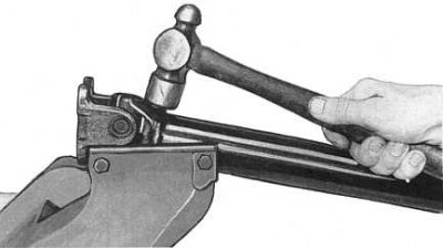
21. Make sure that the joint rotates freely in all directions. If the joint is a little tight, place the driveshaft in a vise and lightly tap the spider holders with a hammer to center the bearings (see accompanying illustration).
22. Repeat the procedures of the last eight paragraphs for the opposite shaft joint. Install the shaft on the car.