1. Using a suitable drift, seat the oil seals into the rear and center crankcases and the input shaft bearing holder flush with the surface of the components. Lubricate the seal lips with a lithium based multipurpose grease.
2. Lubricate all components with clean oil of the required grade.
3. Fit the gear rings, springs and spacers onto the intermediate shaft. make sure that the springs are installed with the concave side towards the gear. Using a press, install the intermediate shaft bearings.
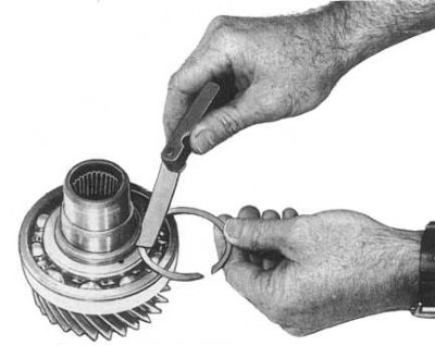
4. Install a spacer on the front of the intermediate shaft and measure the backlash between the circlip and the groove (see accompanying illustration). Compare measurement result with regulatory requirements (see tables of sizes and adjustments at the end of the guide) and select a new retaining ring of the required thickness.
5. Using a press, put the front bearing on the driven shaft (shielded side to output shaft flange).
6. Mount the spacer ring on the driven shaft and measure the backlash between the circlip and the groove. Compare measurement result with regulatory requirements (see tables of sizes and adjustments at the end of the guide) and select a new retaining ring of the required thickness.
7. Lubricate the output shaft front bearing with the correct grade of oil and install the output shaft retainer and front drive sprocket onto the output shaft. Lubricate the roller bearing with oil and rotate the sprocket to fit the bearing onto the shaft.
8. Install the synchronizer sleeve, sliding keys and spring on the front drive sprocket. Make sure that the coupling is installed with a recess from the sprocket, the keys are with short ends. Make sure the keys are properly engaged with the spring.
9. Align the grooves of the synchronizer blocking ring with the keys and put the ring on the drive sprocket. Using a press, install the clutch gear and rear bearing onto the driven shaft. Make sure the bearing is facing the shielded side towards the clutch gear.
10. Using a backplate press, fit the bearings onto the front output and input shafts. Make sure the input shaft bearing outer circlip is facing away from the gear.
11. Install a spacer ring on the input shaft and measure the backlash between the retaining ring and the groove. Compare measurement result with regulatory requirements (see tables of sizes and adjustments at the end of the guide) and select a new retaining ring of the required thickness.
12. Install the inner shift lever oil seal into the front crankcase and lubricate the oil seal lips.
13. Install the inner shift lever to the front crankcase. Install the pin, make sure that the flat segments of the lever are aligned with it, then firmly tighten the mounting nut.

14. Tap the input shaft into the front crankcase using a soft-faced hammer. Lubricate the mating surface of the bearing holder and the threads of the mounting bolts with Loctite 515 (or its equivalent). Tighten the bolts to the required torque (A = 16÷21 Nm; B = 19÷24 Nm - see accompanying illustration). Lubricate the roller bearing with the correct grade of grease and slide it onto the input shaft.
15. Tap the intermediate shaft into the front crankcase with a soft-faced hammer.
16. Install the detent plunger into the front crankcase. Install the shift rods and fork to the up/down shift clutch and insert the assembly into the front crankcase.
17. Lubricate the plugs with sealant and install the retaining balls and springs. Apply sealant to the 4WD signal switch and, on AT models, the start enable switch.
18. Install the spring and bushing into the 2-4 shift fork, making sure the bushing is oriented as before. Install a new retaining ring.
19. Install the mode shift fork 2-4 in the synchronizer sleeve and put the drive chain on the drive sprockets of the driven and output shafts.
20. Align the driven and output shaft assemblies into the center crankcase and use a soft-faced hammer to tap the shafts one at a time until the bearings are fully seated. If necessary, to seat the bearing, install the holder and tighten its bolts. Tighten the bearing holder bolts to the correct torque.
21. Lubricate the roller bearing and install it and the underdrive gear on the output shaft. Using a suitable mandrel, fit the overdrive/reverse hub onto the driven shaft. The hub should be grooved towards the underdrive gear. Install retaining ring.
22. Using a blade-type feeler gauge, measure the clearance between the underdrive gear and the overdrive/underdrive hub. If the air pump end play is out of range (see tables of sizes and adjustments at the end of the guide), remove the gear and hub and replace the defective components.
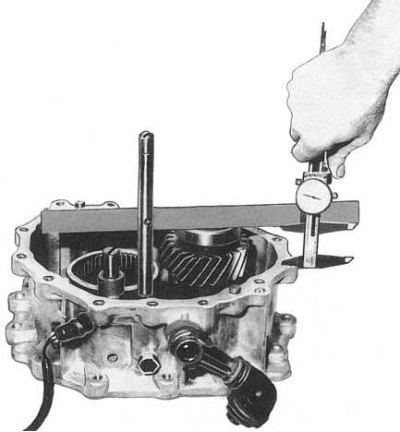
23. Check the amount of axial play of the intermediate shaft (see accompanying illustration):
- Press the flatness tester against the outer race of the countershaft rear bearing and measure the clearance between the mating surface of the front crankcase and the flatness tester rib (see illustration).
- To determine the required thickness of the shim, compare the measurement results with the standard data given in the table:
| Gap size, mm | Adjusting washer thickness, mm |
| 40.6÷40.5 | Washer not required |
| 40.5÷40.4 | 0.1 |
| 40.4÷40.3 | 0.2 |
| 40.3÷40.2 | 0.3 |
| 40.2÷40.1 | 0.4 |
| 40.1÷40.0 | 0.5 |
| 40.0÷39.9 | 0.6 |
- If necessary, install a shim of the required thickness on the intermediate shaft bearing.
24. Lubricate with Loctite 515 (or equivalent) mating surface of the front crankcase and install the center crankcase assembly by guiding the shift yoke onto the shift rod and making sure the shafts are properly positioned.
25. Install the 2-4 shift rod snap ring, oil drain, and speedometer drive gear.
26. Lubricate the internal components of the transfer case with the correct grade of grease.
27. Apply Loctite 515 sealant (or its equivalent) mating surface and install the rear crankcase. Tighten the mounting bolts diagonally to the correct torque and install the speedometer drive assembly.
28. Install the transfer case on the vehicle and tighten the drive flange mounting nuts to the required torque.