


Note: When removing the transfer case components, mark their installation positions - this will make subsequent assembly much easier.
1. Loosen the mounting bolt and remove the speedometer drive assembly.
2. Loosen the mounting bolts and use a pair of levers to remove the rear crankcase from the transfer case (the appearance of the box with the rear casing removed is shown in the accompanying illustration). Take care not to damage the mating surfaces of the components.
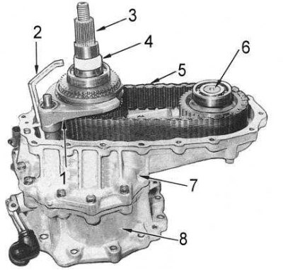
1 - shift fork; 2 - oil drain; 3 - driven shaft; 4 - speedometer drive; 5 - drive chain; 6 - front output shaft; 7 - central crankcase; 8 - front crankcase
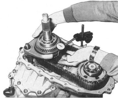
3. Attach the dial gauge to the transfer case by pressing its plunger against the front drive sprocket (see accompanying illustration) and move the sprocket back and forth. Read the indicator reading. If the axial play value is outside the permissible limits (see size and adjustment tables at the end of the Manual), disassemble the driven shaft and carefully examine the condition of the sprocket and associated components. Replace worn or defective parts.
4. Remove the oil drain and remove the speedometer drive gear from the driven shaft.
5. Remove the 2-4 shift fork retaining ring from its rod (the components of the transfer case shift mechanism are shown in the accompanying illustration).
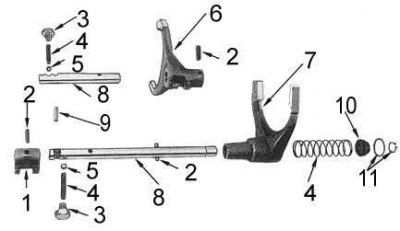
1 - bracket; 2 - pin; 3 - plug; 4 - spring; 5 - ball; 6 - upshift/downshift fork; 7 - 2 - 4 shift fork; 8 - shift rod; 9 - plunger of the lock; 10 - bushing; 11 - retaining rings
6. Loosen the mounting bolts and use a pair of levers to remove the transfer case center housing with the driven shaft assembly from the front housing. Try not to damage the mating surfaces. Remove the adjusting washer from the intermediate shaft rear bearing.
7. Remove the retaining ring and remove the bushing and spring from the 2-4 shift rod. Try to remember the installation position of the bushing. Discard the retaining ring.
8. Using a blade type feeler gauge, measure the clearance between the downshift gear and the upshift/downshift hub (see accompanying illustration). If the axial clearance of the downshift gear is outside the permissible limits, carefully check the condition of the components. Replace any worn or damaged parts.
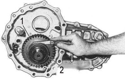
1 - reduction gear
2 — hub of the downshifting/upshifting gear
9. Remove the retaining ring from the front end of the driven shaft.
10. Install the bearing separator between the up/down gear hub and the down gear pinion, slide the puller jaws under the separator and remove the hub (see accompanying illustration). Remove the reduction gear and roller bearing from the driven shaft. Using a T45 head, loosen the bearing retainer screws and knock out the driven and front output shafts one by one until they can be removed from the center crankcase. Remove the drive chain from the driven and front output shafts.
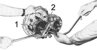
1 - separator
2 - puller
Input and output shaft assembly removed from transfer case

1 - driven shaft; 2 - bearing; 3 - clutch gear; 4 - drive sprocket; 5 - coupling; 6 - holder; 7 - reduction gear; 8 - input shaft
11. Remove the 4WD signal switch from the front crankcase and, on models with AT, the start permission switch (the components of the front transfer case are shown in the accompanying illustration).
12. Unscrew the plugs and remove the springs and retainer balls from the front crankcase.
13. Remove the shift rods, upshift/downshift sleeve and shift fork. Remove the roller bearing from the input shaft. Remove the detent plunger from the detent spring hole.
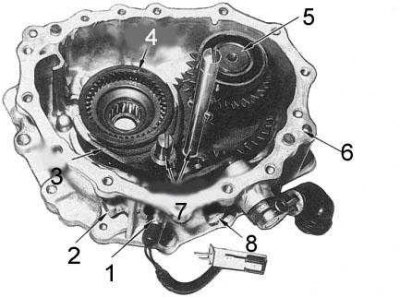
1 - sensor switch; 2 - plug; 3 - fork; 4 - coupling; 5 - intermediate shaft; 6 - front crankcase; 7 - shift rods
14. Loosen the bolts and use a lever to remove the input shaft bearing retainer from the front crankcase.
15. Try not to damage the mating surfaces.
16. Using a soft-faced hammer, knock the intermediate and input shafts out of the front crankcase.
17. Loosen the pin mounting nut and use a soft-faced hammer to strike the end of the nut until the pin partially comes out of the control lever. Remove the nut and pull out the pin.
18. Remove the control lever from the inner shift lever, remove the shift lever from the front housing and use a screwdriver to remove the oil seal. Discard the oil seal.
19. Remove the snap ring and spacer ring, then use a puller and a suitable steel plate to remove the bearing from the input shaft.
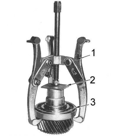
1 - puller
2 - plate
3 - bearing
Input shaft components
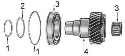
1 - retaining ring; 2 - distance ring; 3 - bearing; 4 - input shaft
20. Using a puller, remove the bearings from the front output shaft (the shaft components are shown in the accompanying illustration):
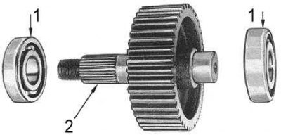
1 - bearing
2 - front output shaft
21. Disassemble the driven shaft (see accompanying illustration):
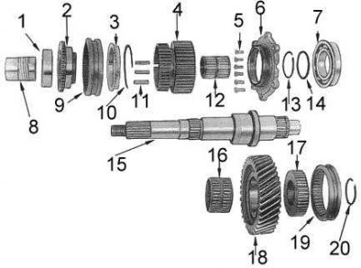
1 - bearing; 2 - clutch gear; 3 - synchronizer locking ring; 4 - drive sprocket; 5 - screws; 6 - holder; 7 - bearing; 8 - speedometer drive; 9 - coupling; 10 - spring; 11 - Sliding keys; 12 - bearing; 13 - retaining ring; 14 - distance ring; 15 - driven shaft; 16 - bearing; 17 - hub of upshift/downshift gears; 18 - reduction gear; 19 - coupling; 20 - retaining ring
- Place the driven shaft in the press, supporting the drive sprocket with the latter's plates. Remove the rear bearing, clutch gear, drive sprocket and synchronizer assembly from the shaft.
- Remove the synchronizer locking ring, then slowly remove the synchronizer sleeve from the drive sprocket, remembering the installation position of the sliding keys. Make sure that the keys with the spring do not jump out during the process of removing the sleeve.
- Remove the bearing retainer, drive sprocket and roller bearing.
- Remove the retaining ring and spacer ring from the driven shaft. Install the shaft in the press, supporting the front bearing with the plates of the latter and remove the bearing from the shaft.
22. Disassemble the intermediate shaft into components (see accompanying illustration):
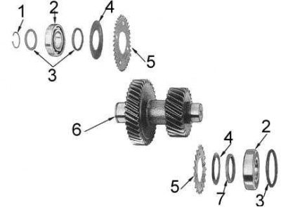
1 - retaining ring; 2 - bearing; 3 - spacer rings; 4 - disc spring; 5 - toothed wheel; 6 - intermediate shaft; 7 - adjusting washer
- Remove the retaining ring and spacer ring from the front end of the intermediate shaft.
- Using a press, remove the front and rear bearings, then remove the spacers, disc springs and toothed rings.
23. Remove the input shaft, then use a puller or a sliding hammer to remove the drive flange seals.