Removal
1. Apply alignment marks to the flanges of the propeller shaft forks, connecting flanges of the main gear and transfer case.
Note: Apply marks with paint.
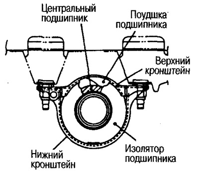
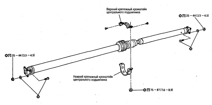
2. Loosen the center bearing bracket mounting nuts.
Caution: Do not loosen the nuts completely.
3. Unscrew the fastening nuts and bolts from the connecting flanges of the propeller shaft, transfer case and final drive. Unscrew the fastening nuts of the central bearing brackets. Then remove the propeller shaft from the vehicle.
Caution: When removing, installing or carrying the driveshaft, the constant velocity joint (CV) boot may be damaged. To protect the boot from damage, wrap the area where the boot contacts metal parts with fabric or rubber.
Examination
1. Fix the fork on one side as shown in the figure, check the axial play of the joint. If the play is different from the norm, replace the cardan shaft assembly.
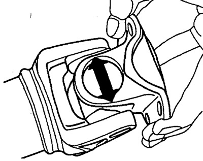
- Maximum clearance: 0 mm
2. Check whether the propeller shaft is bent or damaged. If damage is found, replace the propeller shaft assembly.
3. Check if there is any abnormal noise coming from the bearing or if there is any damage. If abnormal noise or damage is found, replace the propeller shaft assembly.
Attention:
Central bearings (front and back) cannot be disassembled.
The hinges cannot be disassembled.
Installation
Installation is carried out in the reverse order of removal, taking into account the following.
Align the marks placed on the driveshaft prior to removal and tighten the mounting nuts to the required torque.
To avoid longitudinal displacement of the insulator, adjust the position of the bearing brackets.
When tightening bolts and nuts, do not insert the wrench into the joint.
After assembly, perform a road test and check the propeller shaft runout. If runout is detected, separate the propeller shaft from the final drive. Secure the coupling flange by rotating it 90°, 180° or 270°. Then perform a road test again and check the propeller shaft runout in each position.