


Note: The following procedures require the Drive Disc Centering Tool (for installing the clutch) and a puller or a hammer with a sliding striker (to replace the guide bearing bushing).
Removal
1. Remove the transmission from the vehicle.
2. Pull the inner end of the clutch release lever to remove the lever from the spherical support, then remove it together with the rubber protective boot and bearing from the clutch housing.
3. Release the clamp and remove the release bearing assembly with the holder from the clutch release lever.
4. Release the clamp and remove the rubber boot from the release lever (the components of the clutch release mechanism are shown in the accompanying illustration).
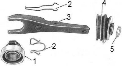
1 - bearing; 2 - clamp; 3 - lever; 4 - case; 5 - clamp
5. Secure the push rod in the clutch slave cylinder to prevent the piston from being pushed out of the cylinder.
6. Mark the position of the clutch basket in relation to the flywheel (it must be observed during assembly).
7. Gradually loosen the mounting bolts and remove the basket assembly and driven disc from the flywheel (the internal components of the clutch are shown in the accompanying illustration).
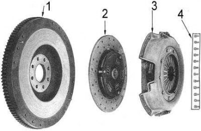
1 - flywheel; 2 - driven shaft; 3 - clutch basket; 4 - bolts
Checking the status of components
1. Inspect the surface of the friction linings of the driven clutch disc. If signs of wear, polished areas or traces of oil contamination are detected, replace the driven disc.
2. If the disc is found to be suitable for further use, do not allow it to become contaminated with oil, grease, cleaning or hydraulic fluid, etc.
Note. When the friction linings wear to a height of 0.3 above the rivet heads, the driven disk must be replaced. If traces of oil are found on the disk, the source of the leak must be identified and eliminated.
3. Make sure that the hub of the driven disk is securely seated. Check the condition of the damper springs.
4. Check the condition of the clutch basket components. Assess the degree of wear of the petals of the diaphragm spring of the pressure plate, check for cracks in them. Inspect the basket body for signs of deformation. Minor defects can be eliminated using fine sandpaper.
5. Inspect the flywheel surface for overheating cracks, burn marks, scratches and scoring. Remove minor defects with fine sandpaper.
Note: A badly damaged flywheel must be replaced.
6. Check the guide bearing bushing at the end of the crankshaft for signs of wear or damage. If necessary, remove the bushing using a puller or a hammer with a sliding striker and install a new one in its place (using a special tool with a stepped mandrel). When installed correctly, the bushing should protrude from the end of the crankshaft by 5.8 mm.
7. Check the condition of the clutch release lever, mounting clamps and spherical support. If signs of severe wear or fatigue information are found, replace defective components.
8. Check the proper functioning of the release bearing (the bearing should rotate freely and silently). The bearing should be removed from the holder only for replacement. A new bearing is installed by pressing in its inner race.
9. Replace all defective components.
Note: When cleaning the clutch components, do not immerse the release bearing in cleaning fluid. The bearing is packed with grease at the factory and does not require additional lubrication.
Installation
Installation is carried out in reverse order.
1. Lightly lubricate the gearbox input shaft journal splines with lithium-based molybdenum disulfide grease. If installing a new driven disc, check for freedom of movement on the input shaft journal splines. Remove the new disc from the shaft and remove it from the components (shaft journal and disc hub) excess grease.
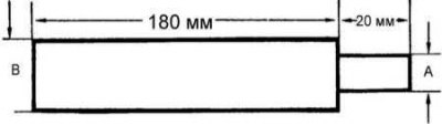
2. Place the driven disc on the flywheel with the protruding sections of the damper springs towards the clutch basket. Fix the disc in the installation position using a special centering tool (a suitable tool can be made from a piece of wood or a round metal rod - see accompanying illustration - dimension A = ø of the centering journal of the primary shaft, B = inner ø of the driven disc hub).
3. If the clutch basket has not been replaced, ensure that the mounting marks made during dismantling are aligned.
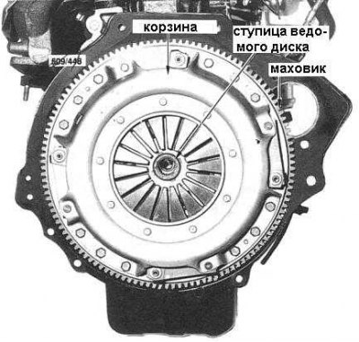
4. Screw in the bolts securing the basket to the flywheel. Tighten the bolts in a diagonal order, evenly in several stages to the required force. The clutch assembly installed on the flywheel is shown in the accompanying illustration.
Note: To avoid damaging the basket mounting bolts, make sure all of them are screwed in before tightening them. Tighten according to the instructions above in this paragraph.
5. Remove the centering tool from the driven disc hub.
6. Lightly lubricate the ends of the clutch release lever and its spherical bearing with lithium-based molybdenum disulfide grease.
7. Using a small amount of the same grease, lubricate the contact points of the release bearing holder and fill the recess in the holder seat.
8. Place the rubber protective cover on the release lever.
9. Connect the release bearing assembly with the holder to the clutch release lever and install the mounting clamp.
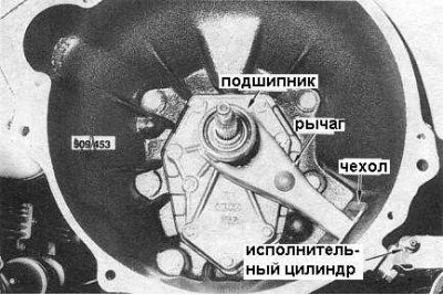
10. Insert the lever assembly with the bearing into the clutch housing, making sure that the mounting clamp snaps firmly onto the lever spherical support (the release mechanism installed in the clutch housing is shown in the accompanying illustration). Also check the reliability of the clamp fastening of the protective cover. Coat the joint of the cover with the surface of the clutch housing with silicone sealant.
11. Loosen the clutch slave cylinder push rod.
12. Install the transmission on the vehicle.
13. Check the adjustment of the height of the position and free travel of the clutch pedal, make adjustments if necessary.