Description
There are five procedures for self-diagnosis. In each of them, control signals are issued, with the help of which it is checked whether there is a malfunction of one or another sensor, and using the corresponding actuator, you can check the operation.
Description of the operation of the self-diagnosis mode
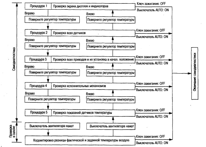
Switching to self-diagnosis mode
Set the rear air conditioner switch to the AUTO position.
Turn the temperature control to the left as far as it will go.
Start the engine (turn the ignition key from OFF to ON) and press the air conditioner switch for at least 5 seconds. The switch must be pressed within 10 seconds. after the engine is started, after which self-diagnosis procedure 1 is started.
Switching between self-diagnosis procedures
Transition from one diagnostic procedure to another (1-5) by turning the temperature controller (HEAT) to the required position.
Turning the knob from left to right: procedures 1-5.
Turning the knob from right to left: procedures 5-1.
Diagnostic content for each procedure: see section «Display in self-diagnosis mode».
Completion of self-diagnosis
Turn the ignition key to the OFF position.
Turn the AUTO switch to the ON position (ON).
Display in self-diagnosis mode
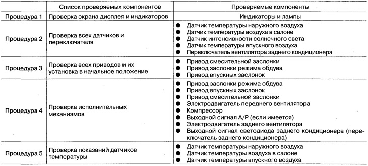
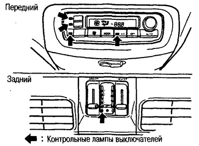
Procedure 1 - Checking the Display Screen and Indicators
The indicators of each switch and the indication on the LCD display are checked.
No fault: Each switch indicator lights up and the LCD displays.
In the event of a malfunction, the corresponding indicator does not flash.
Procedure 2 - Testing All Sensors
When you go to procedure 2, the display shows number 2, followed by the test results. The input signals from all sensors entering the automatic regulator are checked. If all sensors are OK, a code is displayed «20».
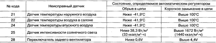
In the event of a fault: the serial number of the faulty sensor flashes after the digit «2». If there is a short circuit in the sensor circuit, the sign lights up «-». In addition, when several sensors are faulty, the sequence numbers flash alternately 2 times.
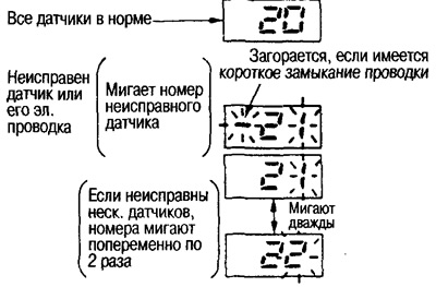
Fault codes and sensor states recognized by the automatic regulator
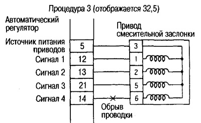
Procedure 3 - Checking All Actuators and Initializing Them
When you go to procedure 3, the number 3 is shown on the display, and then the results of the test are displayed.
The output signals of the drives of the intake and mixing dampers and the blower damper are checked.
If there are no faults, a code is displayed «30».
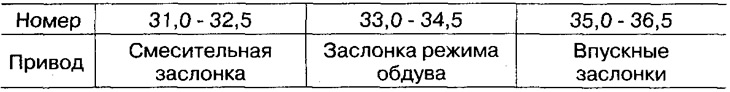
In the event of a fault: the number of the drive with the incorrect damper position flashes. In the event of a short circuit, the indicator lights up «-». In addition, when several positions are incorrect, the sequence numbers flash 2 times alternately.
Press switch to reset all actuators «DEF». This displays the code «30» and for approx. 10 sec. switch indicator flashes «DEF».
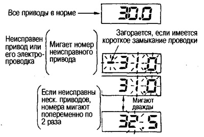 |  |
Indication of faulty drives
Wiring fault indication

Procedure 4 - Checking Actuators
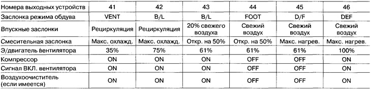
When you go to procedure 4, the number 41 is displayed, and when you press the DEF switch, the indication changes as follows: 42 -> 43-> 44 -> 45 -> 46 -> 41. In addition, the rear fan output changes according to the position of the switch.
As shown in the table, the automatic regulator will force the setting of each drive, blower fan motor and compressor according to the displayed number. Check the operation of the damper by comparing its condition by the sound of operation and touching the corresponding deflector with your hand.
Note: It is not possible to check the operating status of each drive, fan motor, and compressor from the display.
Output device numbers and their states during testing
Front air conditioner
Rear air conditioner
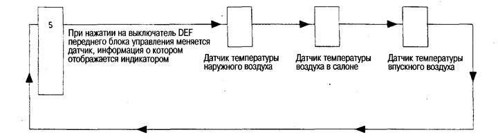
Procedure 5 - Checking Temperature Sensors
When you go to procedure 5, number 5 is displayed. Each time you press the DEF switch, the display of temperature sensors changes with an accuracy of 0.5°C.
Correction of difference between actual and set air temperature
In the event that the air temperature in the passenger compartment differs from the set one, you can adjust the temperature readings. By pressing the fan switch, you can determine the difference between the set (shown on the display) and actual temperature. To adjust, turn the temperature knob. The possible adjustment range is from -3°C to +3°C in 0.5°C increments. If the difference between the given (shown on the display) and the actual temperature is negative, is displayed «AUTO».
Attention: After disconnecting the battery or if the battery voltage drops below 9V, the adjustment described above is erased from memory.