Checking the magnetic clutch system
Checking the magnetic coupling
Disconnect the connector from the air conditioning compressor, check the operation of the compressor magnetic clutch by applying a voltage of approximately 12V to the contacts.
Checking the air conditioner relay
Remove the A/C relay, check the sound of the relay operation by applying a voltage of approximately 12V between pins #1 and #2.
Check if there is continuity between pins #3 and #5.
Checking the amount of refrigerant
Connect the pressure gauge to the vehicle control valve.
Verify that the reading on the low pressure side (pressure gauge) above approx. 0.18 MPa (1.8 kg/cm2).
Checking the ECCS control unit
Start the engine, close contact #28 (models with SR engine) or #21 (models with YD engine) ECCS control unit on «mass», check the operation of the magnetic clutch.
Checking the refrigerant pressure sensor (models with SR engine)
See ch. Engine management system.
Checking the hydraulic switch (models with YD engine)
Disconnect the connector from the hydraulic switch and check its continuity.
Checking the thermal booster
Start the engine, close contact No. 2 on «mass», check the operation of the magnetic clutch.
Checking the air conditioner switch
Disconnect the connector from the regulator, check the continuity between pins #3 and #11.
Checking the fan motor system
Checking the front fan motor
Turn the ignition key to the ON position. Make sure that between terminal #3 of the intermediate wiring of the motor and «weight» there is a voltage of approx. 5V.
Close pins 3 and 4 of the motor and make sure it turns on. If not, repair the motor.
By varying the fan speed from 1 to 4, check the voltage between terminal #4 of the motor and «weight».
- Speed 1: Approx. 1.2V
- Speed 2: Approx. 1.8V
- Speed 3: Approx. 2.6V
- Speed 4: Approx. 4.2V
If the volume of forced air does not change, the electric motor is faulty. If the voltage does not change at different fan speeds, the fan switch or wiring is faulty.
Checking the Front Fan Switch
Disconnect the control unit wiring connector and check the resistance between tracks #7 and #9. If the resistance does not change, the switch is faulty.
- Speed 1: Approx. 3.0 kΣ
- Speed 2: Approx. 2.1 kΣ
- Speed 3: Approx. 1.3 kΣ
- Speed 4: Approx. 0 Σ
Checking the rear fan motor
Disconnect the rear fan connector. Close contact No. 12 of the electric motor on «mass», check its operation by applying a voltage of approx. 12V to pin #1.
By changing the fan speed from LO (low) to HI (high), check the voltage between motor terminal #1 and «weight».
- LO Speed: Approx. 4.5V
- M1 Speed: Approx. 8.0V
- HI Speed: Approx. 12V
If the voltage does not change, the rear fan switch or resistor is faulty.
Checking the Rear Fan Switch
Disconnect the rear A/C harness connector, remove the resistor. Check the continuity between the respective contacts. If there is no continuity, the switch is faulty.
- LO:3 (from the air conditioner) -10 (from the side of the resistor)
- M1:3 (from the air conditioner) - 9 (from the side of the resistor)
- HI: 3 (from the air conditioner) -12 (from the side of the resistor)
Checking the Rear Fan Resistor
Disconnect the connector from the resistor, check the continuity and resistance between the respective pins. If the resistance does not change, the resistor is bad.
- 10-12 (LO): Approx. 16.0
- 9-12 (M1): Approx. 3.1 Σ
Checking the Fan Relay
Remove the fan relay, check the sound of the relay operation by applying a voltage of approx. 12V between pins #1 and #2.
Check if there is continuity between pins #3 and #5.
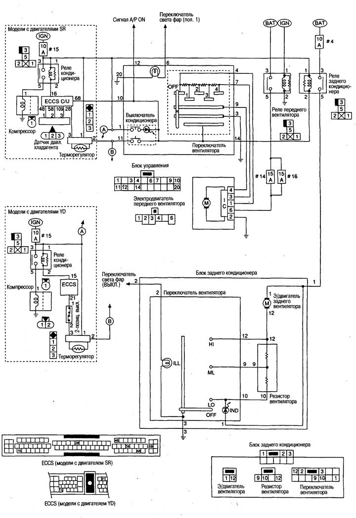
Wiring diagram
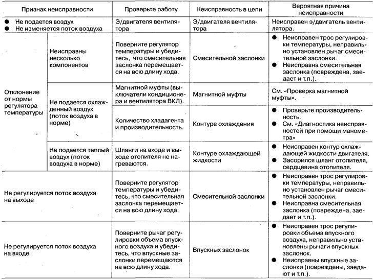
Troubleshooting