2. Turn the ignition key to the ON position and check the voltage between the sensor wiring connectors (pin 1 of sensor 1 and pin 5 of sensor 2) And «weight».
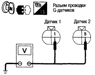
- Voltage: Approx. 8.0V
3. Connect pin 1 of the harness connector and pin 1 of the sensor connector with a wire to apply 8.0 V.
4. Connect pin 3 of the wiring connector and pin 3 of the sensor connector with a wire.
5. Turn the ignition key to the ON position. Measure the output voltage between pins 2 and 3 in three positions: when the sensor is horizontal, when it is rotated 90°forward, when it is rotated 90°back.
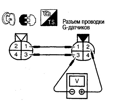
Voltage between pins 2 and 3:
- The sensor is located horizontally: 2.3-2.7 V
- Sensor rotated 90°forward: 0.80-0.86
- Sensor rotated 90°back: 3.87-4.47
6. Connect pin 5 of the harness connector and pin 5 of the sensor connector with a wire to apply 8.0 V.
7. Connect pin 7 of the wiring connector and pin 7 of the sensor connector with a wire.
8. Turn the ignition key to the ON position. Measure the output voltage between pins 6 and 7 in three positions: when the sensor is horizontal, when it is rotated 90°forward, when it is rotated 90°back.
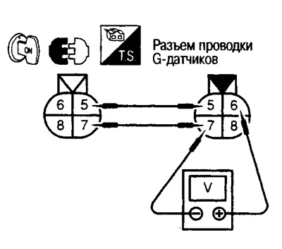
Voltage between pins 6 and 7:
- The sensor is located horizontally: 2.3-2.7 V
- Sensor rotated 90°forward: 0.80-0.86
- Sensor rotated 90°back: 3.87-4.47
9. After completing the check, install the sensors and erase the fault codes from the memory of the ABS control unit.